
DETERMINATION OF YOUNG'S MODULUS BY BEAM BENDING METHOD
1. AIM
To determine the Young's modulus of elasticity of the material of a given beam using the beam bending method.
2. APPARATUS USED
- Rectangular beam of the material under test (usually metal)
- Two knife edges for support
- Traveling microscope or dial gauge
- Meter scale
- Micrometer screw gauge
- Vernier caliper
- Set of standard weights
- Weight hanger
- Graph paper
- Spirit level
3. DIAGRAM
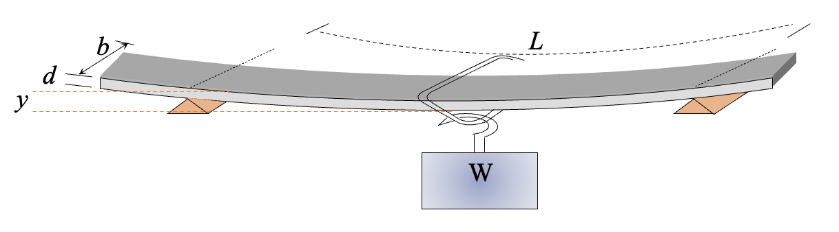
4. THEORY
Young's modulus (E) is a measure of the stiffness of a material and is defined as the ratio of stress to strain in the elastic region of deformation.
When a beam is supported at two ends and loaded at its center, it bends. The amount of bending (deflection) depends on:
- The applied load
- The length of the beam
- The cross-sectional dimensions of the beam
- The Young's modulus of the material
For a beam with rectangular cross-section, supported at two points and loaded at the center, the relationship between the deflection and Young's modulus is given by the theory of elasticity. As the beam bends, the upper surface is compressed while the lower surface is stretched. There exists a neutral surface that experiences neither compression nor extension.
The deflection of the beam is inversely proportional to the Young's modulus of the material, allowing us to calculate E from measurements of the beam's deflection under various loads.
5. FORMULA
For a beam of rectangular cross-section supported at two points and loaded at the center, the Young's modulus is given by:
Where:
- \(E\) = Young's modulus of elasticity (N/m²)
- \(W\) = Load applied at the center of the beam (N)
- \(L\) = Length of the beam between the supports (m)
- \(b\) = Breadth/width of the beam (m)
- \(d\) = Depth/height of the beam (m)
- \(y\) = Deflection produced at the center of the beam (m)
6. PROCEDURE
Measure the dimensions of the beam (length L, breadth b, and depth d) using a meter scale, vernier caliper, and micrometer screw gauge.
Place the beam horizontally on two knife edges that are at a distance L apart.
Ensure the beam is level using a spirit level.
Set up the traveling microscope or dial gauge beneath the center of the beam to measure deflection.
Note the initial reading of the microscope/gauge without any load (zero load reading).
Place the weight hanger at the center of the beam.
Add weights in steps (e.g., 100g, 200g, 300g, etc.) to the hanger.
For each load, record the reading of the microscope/gauge after the beam has stabilized.
Calculate the deflection for each load by finding the difference between the loaded and unloaded readings.
Plot a graph of load (W) versus deflection (y). This should be a straight line if the beam remains in the elastic region.
Remove the weights gradually and check if the beam returns to its original position to confirm the deformation was elastic.
Calculate Young's modulus using the formula.
7. OBSERVATION TABLE
A. Measurement of Beam Dimensions:
| Parameter | Reading 1 | Reading 2 | Reading 3 | Mean Value |
|---|---|---|---|---|
| Length (L) in m | ||||
| Breadth (b) in m | ||||
| Depth (d) in m |
B. Measurement of Deflection:
| S.No. | Load W (N) | Microscope/Gauge Reading (m) | Deflection y (m) |
|---|---|---|---|
| 1 | 0 (Initial) | 0 | |
| 2 | |||
| 3 | |||
| 4 | |||
| 5 | |||
| 6 |
8. CALCULATIONS
-
For each load, calculate the deflection y by subtracting the initial reading from the corresponding microscope/gauge reading.
-
Plot a graph of load (W) versus deflection (y).
-
Calculate the slope of the graph (ΔW/Δy).
-
Calculate Young's modulus using the formula:
$$E = \frac{W \times L^3}{4 \times b \times d^3 \times y}$$Alternatively, using the slope of the graph:
$$E = \frac{L^3}{4 \times b \times d^3} \times \frac{\Delta W}{\Delta y}$$ -
Express the final result in appropriate units (typically GPa or N/m²).
9. RESULT
The Young's modulus of elasticity (E) of the material of the given beam is _____ N/m² or _____ GPa.
10. PRECAUTIONS
The beam should be placed symmetrically on the knife edges.
The load should be applied exactly at the center of the beam.
The surface of the beam should be smooth and uniform without any defects.
The beam should not be loaded beyond its elastic limit.
The beam should return to its original position when all weights are removed.
The microscope/gauge should be positioned directly beneath the center of the beam.
Allow the beam to stabilize after each load addition before taking readings.
Avoid jerky movements or vibrations while taking readings.
Measurements of dimensions should be taken multiple times and averaged for accuracy.
The knife edges should be at exactly the same height.
11. VIVA VOICE QUESTIONS
What is Young's modulus? How is it related to stress and strain?
Why is the beam supported at two ends instead of being fixed at one end?
What happens if the load exceeds the elastic limit of the material?
How does the deflection depend on the length of the beam?
Why is the deflection inversely proportional to the cube of the depth of the beam?
What would happen if the beam were not placed symmetrically on the supports?
How would the result change if the beam were made of a different material?
Why is it important to measure the dimensions of the beam accurately?
What are the potential sources of error in this experiment?
How do temperature changes affect Young's modulus measurements?
What is the difference between elastic and plastic deformation?
Can this method be used for any material? What are its limitations?
How would the formula change if the load were not applied at the center of the beam?
What is the relationship between Young's modulus and the stiffness of a material?
How would you verify that the beam remains in the elastic region throughout the experiment?