
To study the current-voltage (I-V) characteristics of a Light Emitting Diode (LED) and determine its forward voltage, threshold current, and operating parameters.
- Light Emitting Diode (different colors if available: Red, Green, Blue, White)
- DC Power Supply (0-12V variable)
- Digital Ammeter (0-200mA range)
- Digital Voltmeter (0-20V range)
- Rheostat (1kΩ)
- Connecting wires
- Breadboard
- Series resistor (220Ω or 330Ω)
- Lux meter (optional: for light intensity measurement)
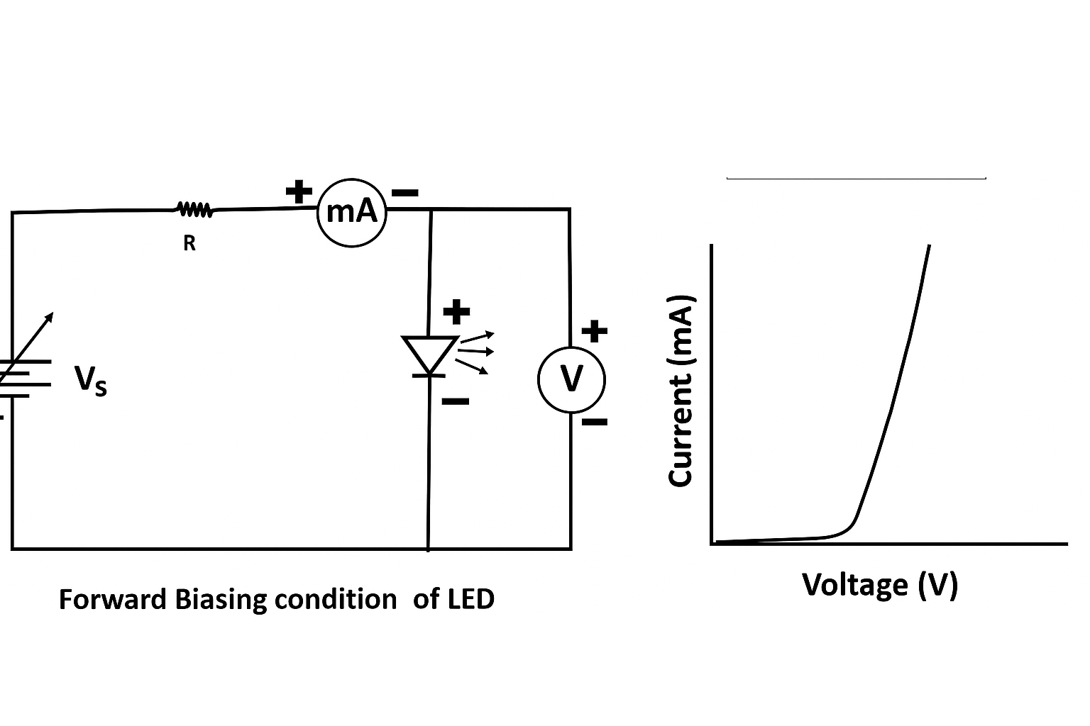
Fig 1: Circuit diagram for Light Emitting Diode characteristics measurement
A Light Emitting Diode (LED) is a semiconductor device that emits light when an electric current passes through it. The LED is a specialized type of PN junction diode that converts electrical energy into light energy through a process called electroluminescence.
When a forward bias voltage is applied to an LED, electrons from the n-region and holes from the p-region are pushed toward the junction. When electrons recombine with holes, they fall to lower energy levels and release energy in the form of photons (light). The color (wavelength) of the light emitted depends on the band gap energy of the semiconductor materials used in the LED.
The primary materials used for LEDs include:
- Gallium Arsenide (GaAs)
- Gallium Phosphide (GaP)
- Gallium Arsenide Phosphide (GaAsP)
- Aluminum Gallium Indium Phosphide (AlGaInP)
- Gallium Nitride (GaN)
- Indium Gallium Nitride (InGaN)
The I-V characteristics of an LED are similar to a normal diode, but with a typically higher forward voltage drop. This voltage drop (turn-on voltage) depends on the color of the LED:
- Red LED: 1.8-2.1 V
- Green LED: 2.0-2.2 V
- Blue LED: 2.5-3.0 V
- White LED: 3.0-3.5 V
The brightness or intensity of the light emitted by an LED is approximately proportional to the forward current flowing through it. However, a series resistor is typically used to limit the current and prevent damage to the LED.
The following formulas are relevant for this experiment:
1. Current limiting resistor value:
$$R_s = \frac{V_{supply} - V_f}{I_f}$$
Where:
- \(R_s\) = Series resistance in ohms (Ω)
- \(V_{supply}\) = Supply voltage in volts (V)
- \(V_f\) = Forward voltage of LED in volts (V)
- \(I_f\) = Forward current through LED in amperes (A)
2. Power dissipated by the LED:
$$P_{LED} = V_f \times I_f$$
Where:
- \(P_{LED}\) = Power dissipated by LED in watts (W)
- \(V_f\) = Forward voltage across LED in volts (V)
- \(I_f\) = Forward current through LED in amperes (A)
3. LED forward current can be approximated by the Shockley diode equation:
$$I_f = I_s \left( e^{\frac{qV_f}{nkT}} - 1 \right)$$
Where:
- \(I_s\) = Reverse saturation current
- \(q\) = Electron charge (1.602 × 10^-19 coulombs)
- \(V_f\) = Forward voltage
- \(n\) = Ideality factor (typically 1-2 for LEDs)
- \(k\) = Boltzmann constant (1.381 × 10^-23 J/K)
- \(T\) = Temperature in Kelvin
- Set up the circuit as shown in the diagram. Connect the LED with the correct polarity (longer lead is the anode, shorter lead is the cathode).
- Include a series resistor (220Ω or 330Ω) to protect the LED from excessive current.
- Ensure that the power supply is set to zero volts before making connections.
- Connect the ammeter in series with the LED to measure the forward current.
- Connect the voltmeter in parallel with the LED to measure the forward voltage.
- Gradually increase the supply voltage using the rheostat, starting from 0V.
- Record the forward voltage (Vf) and forward current (If) at each step.
- Continue until you have readings covering the LED's operating range (typically up to 20mA for standard LEDs).
- If available, use a lux meter to measure the light intensity at each current value.
- Turn off the power supply and carefully disassemble the circuit when finished.
- Plot a graph of forward current (If) versus forward voltage (Vf).
- If measured, plot a graph of light intensity versus forward current.
| S.No. | Supply Voltage (Vs) Volts |
Forward Voltage (Vf) Volts |
Forward Current (If) mA |
Light Intensity (Optional) Lux |
|---|---|---|---|---|
| 1 | ||||
| 2 | ||||
| 3 | ||||
| 4 | ||||
| 5 | ||||
| 6 | ||||
| 7 | ||||
| 8 | ||||
| 9 | ||||
| 10 |
From the observation table, we can determine several parameters:
1. Threshold Voltage (Vth):
The forward voltage at which the LED begins to conduct significantly (usually when current reaches ~1mA).
From the table, Vth = ________ V
2. Dynamic Resistance (rd):
The dynamic or AC resistance of the LED in its conducting region:
$$r_d = \frac{\Delta V_f}{\Delta I_f}$$
Taking two points from the linear region of the I-V curve:
For Vf1 = _____ V, If1 = _____ mA
For Vf2 = _____ V, If2 = _____ mA
Dynamic resistance, rd = (Vf2 - Vf1)/(If2 - If1) = ________ Ω
3. Power Dissipation (P):
At operating point (e.g., If = 15mA):
P = Vf × If = _____ V × _____ mA = _____ mW
4. Series Resistor Calculation:
For a supply voltage of Vs = _____ V and desired LED current of If = _____ mA:
Rs = (Vs - Vf)/If = (_____ V - _____ V)/_____ mA = _____ Ω
Based on the experiment, the following results were obtained:
- The threshold voltage (Vth) of the LED is _____ V.
- The LED shows a forward voltage (Vf) of approximately _____ V at a typical operating current of 15mA.
- The dynamic resistance (rd) of the LED in its operating region is _____ Ω.
- The LED emits _____ colored light when forward biased above its threshold voltage.
- The I-V characteristic curve confirms that the LED behaves like a diode with exponential current growth beyond the threshold voltage.
- The light intensity was observed to increase with increasing forward current, showing a nearly linear relationship in the normal operating range.
The experiment successfully demonstrated the current-voltage characteristics of an LED and verified its fundamental operation as a light-emitting semiconductor device.
- Always connect the Light Emitting Diode with the correct polarity (anode to positive, cathode to negative).
- Never connect an Light Emitting Diode directly to a power supply without a current-limiting resistor.
- Do not exceed the maximum forward current rating of the Light Emitting Diode (typically 20-30mA for standard LEDs).
- Increase the voltage gradually to avoid sudden current surges.
- Ensure all connections are secure before applying power.
- Turn off the power supply before modifying the circuit.
- Handle the Light Emitting Diode carefully as the leads are fragile.
- Avoid looking directly at very bright LEDs, especially high-power or UV LEDs.
- Keep the circuit away from water and moisture.
- Do not touch the circuit components while the power is on.
Q1. What is a Light Emitting Diode (LED)?
A Light Emitting Diode (LED) is a semiconductor device that emits light when an electric current passes through it. It is a specialized P-N junction diode that converts electrical energy to light energy through the process of electroluminescence.
Q2. How does an Light Emitting Diode differ from a normal P-N junction diode?
Unlike regular diodes which are made of silicon or germanium, LEDs are made from direct band gap semiconductor materials like gallium arsenide phosphide (GaAsP) or gallium nitride (GaN). LEDs emit light when forward biased due to electron-hole recombination, while normal diodes do not emit visible light. LEDs also typically have a higher forward voltage drop compared to regular diodes.
Q3. What determines the color of light emitted by an Light Emitting Diode?
The color of light emitted by an Light Emitting Diode is determined by the band gap energy of the semiconductor material used. Different semiconductor compounds produce different wavelengths of light when electrons recombine with holes. The wavelength (and thus color) is inversely proportional to the band gap energy.
Q4. Why is a series resistor necessary when connecting an Light Emitting Diode to a power source?
A series resistor is needed to limit the current flowing through the Light Emitting Diode. Without a current-limiting resistor, the Light Emitting Diode would draw excessive current and could be damaged or destroyed due to overheating, as the LED has a very low internal resistance when forward biased above its threshold voltage.
Q5. What is the relationship between forward current and light output in an Light Emitting Diode?
In general, the light output (luminous intensity) of an Light Emitting Diode is approximately proportional to the forward current flowing through it. However, this relationship is not perfectly linear, especially at higher currents where efficiency may decrease due to heating effects.
Q6. How can you identify the anode and cathode of an Light Emitting Diode without any markings?
In a standard LED, the longer lead is typically the anode (positive), and the shorter lead is the cathode (negative). Additionally, inside the Light Emitting Diode package, the cathode side usually has a larger metal part (reflector cup) that holds the semiconductor die.
Q7. Why do different colored LEDs have different forward voltage drops?
Different colored LEDs have different forward voltage drops because they are made from different semiconductor materials with varying band gap energies. LEDs emitting higher energy photons (blue, white) require a larger band gap material, which in turn requires a higher forward voltage to overcome the energy barrier.
Q8. What happens if you reverse the polarity of voltage applied to an Light Emitting Diode?
If reverse voltage is applied to an LED, it will not conduct significant current and will not emit light. If the reverse voltage exceeds the LED's breakdown voltage (typically 3-5V), the LED may be permanently damaged due to excessive current flow and overheating.
Q9. How does temperature affect the performance of an Light Emitting Diode?
Increased temperature negatively affects Light Emitting Diode performance. As temperature rises, the LED's forward voltage decreases slightly, efficiency decreases, light output decreases, and the LED's lifetime can be significantly reduced. This is why heat sinking is important for high-power LEDs.
Q10. What are the advantages of LEDs over conventional light sources?
LEDs offer numerous advantages including higher energy efficiency, longer lifespan (up to 100,000 hours), smaller size, faster switching, directional light emission, durability against shock and vibration, no UV emissions (unless specifically designed to emit UV), low heat generation, and the ability to produce specific colors without filters.