
FORWARD CHARACTERISTICS OF POINT CONTACT DIODE
1. AIM
To study and plot the forward bias characteristics of a point contact diode and determine its static and dynamic resistance.
2. APPARATUS USED
- Point Contact Diode (Germanium diode, e.g., OA79, 1N34A)
- DC Power Supply (0-5V, variable)
- Voltmeter (0-3V DC range)
- Milliammeter (0-50mA range)
- Resistor (470Ω, 1W)
- Rheostat/Potentiometer (1kΩ)
- Connecting wires and breadboard
- Graph paper for plotting characteristics
3. DIAGRAM
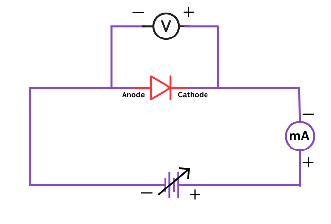
Fig. 1: Circuit diagram for studying the forward characteristics of point contact diode
4. THEORY
A point contact diode consists of a small metal wire (usually tungsten or phosphor bronze) making point contact with a semiconductor material (typically n-type germanium). The point contact creates a p-n junction at the interface between the metal and semiconductor.
When a diode is forward biased (positive potential to the p-side and negative to the n-side), the barrier potential decreases, allowing current to flow through the diode. As the forward voltage increases, the current increases exponentially according to the diode equation.
Point contact diodes have some distinctive characteristics compared to p-n junction diodes:
- Lower forward voltage drop (typically 0.2V for germanium point contact diodes)
- Faster switching times due to lower junction capacitance
- Higher reverse current leakage
- Less mechanical robustness
The forward characteristics of a point contact diode follow the Shockley diode equation:
Where:
- $I$ = Forward current through the diode
- $I_S$ = Reverse saturation current
- $V$ = Applied voltage across the diode
- $q$ = Charge of an electron (1.602 × 10⁻¹⁹ C)
- $k$ = Boltzmann's constant (1.38 × 10⁻²³ J/K)
- $T$ = Absolute temperature in Kelvin
- $n$ = Ideality factor (typically between 1 and 2)
At room temperature (around 300K) and for voltage values much greater than the thermal voltage (kT/q ≈ 26mV), the equation can be simplified to:
This relationship gives rise to the exponential I-V characteristic curve observed in diodes.
5. FORMULA
1. Static Resistance: The ratio of the DC voltage across the diode to the DC current through the diode at a particular operating point.
2. Dynamic or AC Resistance: The ratio of a small change in voltage to the corresponding change in current at a particular operating point.
3. From the theoretical diode equation, the dynamic resistance can also be calculated as:
Where $V_T = \frac{kT}{q} \approx 26$ mV at room temperature.
6. PROCEDURE
- Set up the circuit as shown in the diagram (Figure 1). Ensure that the diode is connected with correct polarity for forward bias (anode to positive and cathode to negative).
- Before turning on the power supply, set the rheostat/potentiometer to its maximum resistance position to ensure minimum current flows initially.
- Turn on the power supply and adjust it to a low voltage (around 0.5V).
- Gradually decrease the resistance of the rheostat to increase the current through the diode.
- Record the voltmeter reading (V) and the corresponding milliammeter reading (I) for different values of current. Start from 0V and increase in small steps (0.05V increments recommended for the crucial knee region around 0.2-0.3V).
- Continue taking readings until the forward voltage reaches about 0.8V or the current reaches the maximum safe value for the diode (typically 50mA for small signal diodes).
- Record all readings in the observation table.
- Turn off the power supply after completing all measurements.
- Plot a graph between the forward voltage (x-axis) and forward current (y-axis).
- Calculate the static and dynamic resistance at different points on the curve.
7. OBSERVATION TABLE
| Sl. No. | Forward Voltage (V) Volts | Forward Current (I) mA | Static Resistance (Rs = V/I) Ohms | Dynamic Resistance (rd = ΔV/ΔI) Ohms |
|---|---|---|---|---|
| 1 | — | |||
| 2 | ||||
| 3 | ||||
| 4 | ||||
| 5 | ||||
| 6 | ||||
| 7 | ||||
| 8 | ||||
| 9 | ||||
| 10 |
Note: Dynamic resistance can be calculated using consecutive readings as ΔV/ΔI
8. CALCULATIONS
Sample calculation for static resistance:
For a particular reading, if V = 0.3V and I = 10mA (0.01A):
Sample calculation for dynamic resistance:
For two consecutive readings:
Reading 1: V1 = 0.25V, I1 = 5mA
Reading 2: V2 = 0.3V, I2 = 10mA
Theoretical calculation of dynamic resistance:
For a point where I = 10mA and assuming n = 1.2 for a germanium point contact diode at room temperature (300K):
9. RESULT
1. The forward characteristic (I-V curve) of the point contact diode has been plotted, showing the exponential relationship between voltage and current.
2. The knee voltage (threshold voltage) of the germanium point contact diode was found to be approximately _____ volts.
3. The static resistance values were calculated at different operating points and found to decrease with increasing forward current, ranging from _____ Ω to _____ Ω.
4. The dynamic resistance values were calculated and found to be consistently lower than the static resistance values, ranging from _____ Ω to _____ Ω.
5. The experimental values of resistance were found to be in reasonable agreement with the theoretically expected values, with discrepancies attributed to temperature variations and component tolerances.
10. PRECAUTIONS
- Always connect the diode with the correct polarity in the circuit. Reverse connection can damage the diode in the presence of high voltage.
- Start with minimum voltage and gradually increase it to avoid sudden current surges through the diode.
- Do not exceed the maximum current rating of the diode. For most point contact diodes, this is typically around 50mA.
- Use appropriate range of voltmeter and milliammeter to get accurate readings.
- Ensure all connections are tight and secure before starting the experiment.
- Handle the point contact diode carefully as they are mechanically fragile compared to junction diodes.
- Allow some time between consecutive readings to prevent heating of the diode, which can affect its characteristics.
- Turn off the power supply when changing connections.
- Take more readings around the knee voltage region (0.2-0.3V for germanium diodes) for better characterization.
- Keep the circuit away from heat sources as diode characteristics are temperature-dependent.