
To Study Photodiode Characteristics
1. Aim
To study the I-V characteristics of a photodiode under different light intensities and analyze its operation in photovoltaic and photoconductive modes.
2. Apparatus Used
- Photodiode (e.g., BPW34, OPT301, or similar)
- Variable DC power supply (0-15V)
- Digital multimeter (for current measurement)
- Digital voltmeter (0-20V range)
- Variable light source (preferably with intensity control)
- Light meter or Lux meter (for measuring light intensity)
- Resistors (1kΩ, 10kΩ)
- Connecting wires and breadboard
- Optical bench (optional, for maintaining fixed distances)
3. Diagram
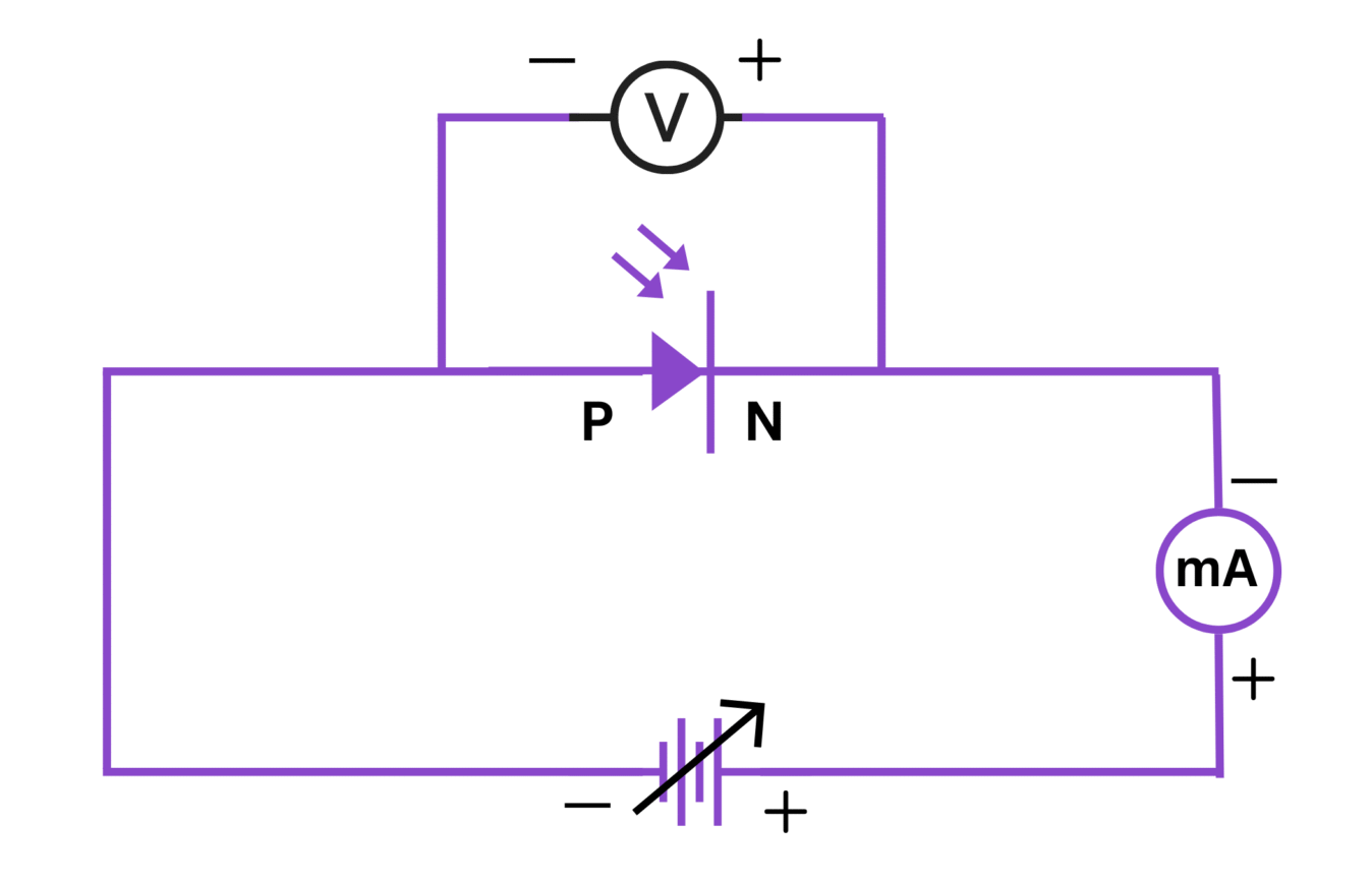
Fig. 1: Experimental setup for studying photodiode characteristics
4. Theory
A photodiode is a semiconductor device that converts light energy into electrical current. It is designed to operate in reverse bias and exhibits properties that make it suitable for light detection applications.
Working Principle:
Photodiodes operate based on the photoelectric effect, where photons with energy greater than or equal to the band gap of the semiconductor material generate electron-hole pairs when they strike the device. These carriers are then separated by the built-in electric field in the depletion region, creating a photocurrent.
Operating Modes:
- Photovoltaic Mode: The photodiode operates with zero bias (short circuit) or small reverse bias. In this mode, the photodiode generates a voltage when exposed to light, similar to a solar cell.
- Photoconductive Mode: The photodiode operates with reverse bias. This mode provides faster response times, lower junction capacitance, and better linearity at the expense of increased dark current.
Characteristic Parameters:
- Dark Current (ID): The small current that flows through the photodiode when no light is incident on it.
- Photocurrent (IP): The current generated due to incident light.
- Total Current (I): The sum of dark current and photocurrent (I = ID + IP).
- Responsivity (R): The ratio of generated photocurrent to incident light power, usually expressed in A/W.
- Quantum Efficiency (η): The ratio of generated electron-hole pairs to incident photons.
5. Formula
The total current through a photodiode can be represented as:
\[ I = I_0 \left( e^{\frac{qV}{nkT}} - 1 \right) - I_P \]
Where:
- \( I_0 \) = Reverse saturation current
- \( q \) = Electronic charge (1.6 × 10⁻¹⁹ C)
- \( V \) = Applied voltage
- \( n \) = Ideality factor
- \( k \) = Boltzmann's constant (1.38 × 10⁻²³ J/K)
- \( T \) = Temperature in Kelvin
- \( I_P \) = Photocurrent
The photocurrent is directly proportional to the incident light intensity:
\[ I_P = R \cdot P \]
Where:
- \( R \) = Responsivity of the photodiode (A/W)
- \( P \) = Incident optical power (W)
Responsivity can be calculated as:
\[ R = \frac{\eta \cdot q \cdot \lambda}{h \cdot c} \]
Where:
- \( \eta \) = Quantum efficiency
- \( \lambda \) = Wavelength of incident light (m)
- \( h \) = Planck's constant (6.626 × 10⁻³⁴ J⋅s)
- \( c \) = Speed of light (3 × 10⁸ m/s)
6. Procedure
- Set up the circuit as shown in the diagram with the photodiode connected to the DC power supply and the ammeter in series.
- Ensure that the experiment is performed in controlled lighting conditions.
- Dark Characteristics:
- Cover the photodiode completely to ensure no light falls on it.
- Apply reverse bias voltage starting from 0V and increase in steps of 0.5V up to 10V.
- Record the dark current for each voltage step in Table 1.
- Light Characteristics (Varying Intensity):
- Setup the light source at a fixed distance from the photodiode.
- Use the light meter to measure the light intensity in lux.
- For each light intensity level (e.g., Low, Medium, High), record the corresponding lux reading.
- Apply reverse bias voltage from 0V to 10V in steps of 0.5V and record the current for each level in Tables 2, 3, and 4.
- Light Characteristics (Varying Distance):
- Set the light source to a fixed intensity.
- Vary the distance between the light source and the photodiode.
- For each distance, measure the light intensity using the lux meter.
- Apply reverse bias of 5V and record the current for each distance in Table 5.
- Photovoltaic Mode:
- Connect the photodiode directly to the voltmeter (without any bias).
- Vary the light intensity and record the open-circuit voltage generated by the photodiode in Table 6.
- Plot the following graphs:
- I-V characteristic curves for different light intensities.
- Photocurrent vs. Light intensity at constant bias voltage.
- Photocurrent vs. Distance at constant bias voltage.
7. Observation Tables
Table 1: Dark Characteristics
| Reverse Bias Voltage (V) | Dark Current (μA) |
|---|---|
| 0.0 | |
| 0.5 | |
| 1.0 | |
| 1.5 | |
| 2.0 | |
| 3.0 | |
| 4.0 | |
| 5.0 | |
| 6.0 | |
| 8.0 | |
| 10.0 |
Table 2: Light Characteristics - Low Intensity (______ lux)
| Reverse Bias Voltage (V) | Current (μA) | Photocurrent (μA) = Total Current - Dark Current |
|---|---|---|
| 0.0 | ||
| 0.5 | ||
| 1.0 | ||
| 2.0 | ||
| 3.0 | ||
| 5.0 | ||
| 7.0 | ||
| 10.0 |
Table 3: Light Characteristics - Medium Intensity (______ lux)
| Reverse Bias Voltage (V) | Current (μA) | Photocurrent (μA) = Total Current - Dark Current |
|---|---|---|
| 0.0 | ||
| 0.5 | ||
| 1.0 | ||
| 2.0 | ||
| 3.0 | ||
| 5.0 | ||
| 7.0 | ||
| 10.0 |
Table 4: Light Characteristics - High Intensity (______ lux)
| Reverse Bias Voltage (V) | Current (μA) | Photocurrent (μA) = Total Current - Dark Current |
|---|---|---|
| 0.0 | ||
| 0.5 | ||
| 1.0 | ||
| 2.0 | ||
| 3.0 | ||
| 5.0 | ||
| 7.0 | ||
| 10.0 |
Table 5: Photocurrent vs. Distance (at 5V Reverse Bias)
| Distance (cm) | Light Intensity (lux) | Total Current (μA) | Photocurrent (μA) |
|---|---|---|---|
| 10 | |||
| 15 | |||
| 20 | |||
| 25 | |||
| 30 | |||
| 40 | |||
| 50 |
Table 6: Photovoltaic Mode (Open-Circuit Voltage)
| Light Intensity (lux) | Open-Circuit Voltage (mV) |
|---|---|
| Dark (0) | |
| Low (______ lux) | |
| Medium (______ lux) | |
| High (______ lux) |
8. Calculations
- Photocurrent Calculation:
Photocurrent (IP) = Total current (I) - Dark current (ID)
Sample calculation:
If at 5V reverse bias:
- Dark current (ID) = ____ μA
- Total current at medium intensity (I) = ____ μA
- Therefore, Photocurrent (IP) = ____ μA - ____ μA = ____ μA
- Responsivity Calculation:
\[ R = \frac{I_P}{P} \]
Where:
- IP = Photocurrent (A)
- P = Incident optical power (W)
Note: To convert from lux to W/m², use the approximation: 1 lux ≈ 1.464 × 10⁻³ W/m² for visible light.
To get power on the photodiode, multiply by the active area of the photodiode.
Sample calculation:
If the active area of the photodiode is 7.5 mm²:
\[ P = \text{Light intensity (W/m²)} \times \text{Active area (m²)} \]
\[ P = \text{Light intensity (lux)} \times 1.464 \times 10^{-3} \times 7.5 \times 10^{-6} \]
- Inverse Square Law Verification:
According to the inverse square law, light intensity is inversely proportional to the square of the distance:
\[ I \propto \frac{1}{d^2} \]
Therefore:
\[ I_1 \times d_1^2 = I_2 \times d_2^2 \]
Verify this relationship using the data from Table 5.
9. Result
- The I-V characteristics of the photodiode have been successfully plotted for different light intensities.
- The dark current of the photodiode was found to be approximately _____ μA at 5V reverse bias.
- The photocurrent was directly proportional to the light intensity, increasing from _____ μA at low intensity to _____ μA at high intensity (at 5V reverse bias).
- The responsivity of the photodiode was calculated to be approximately _____ A/W.
- In photovoltaic mode, the open-circuit voltage increased from _____ mV at low intensity to _____ mV at high intensity.
- The inverse square law relationship between light intensity and distance was verified with an average error of _____.
10. Precautions
- Avoid exposing the photodiode to very intense light as it may damage the device.
- Ensure proper connections and polarities when connecting the photodiode in the circuit.
- Perform the experiment in controlled lighting conditions to avoid interference from ambient light.
- Keep the light source stable during measurements to ensure consistent results.
- Use appropriate current ranges on the multimeter to get accurate readings, especially for low-level dark currents.
- Handle the photodiode with care as it is sensitive to static electricity.
- Allow sufficient warming-up time for the light source to stabilize before taking measurements.
- Ensure that the photodiode is properly shielded when measuring dark current.
- Maintain a constant temperature throughout the experiment as photodiode characteristics are temperature-dependent.
- Record the readings promptly to avoid errors due to drift in light intensity or temperature.
11. Viva Voice Questions
Q1. What is a photodiode and how does it differ from a normal PN junction diode?
A photodiode is a semiconductor device that converts light energy into electrical current. Unlike a normal PN junction diode that is enclosed in an opaque package, a photodiode has a transparent window or lens that allows light to reach the PN junction. Additionally, photodiodes are optimized for light detection with a larger depletion region and are usually operated in reverse bias for better performance.
Q2. Explain the difference between photoconductive and photovoltaic modes of operation.
In photoconductive mode, the photodiode operates with reverse bias, resulting in increased sensitivity, faster response time, and better linearity but with higher dark current. In photovoltaic mode, the photodiode operates with zero bias (or very small bias), generating a voltage in response to light similar to a solar cell, with lower dark current but slower response time.
Q3. What is dark current in a photodiode?
Dark current is the small leakage current that flows through a photodiode when no light is incident on it. It is primarily due to thermally generated electron-hole pairs in the depletion region and surface leakage currents. Dark current increases with temperature and reverse bias voltage.
Q4. Define responsivity of a photodiode and explain its significance.
Responsivity is the ratio of generated photocurrent to incident optical power, typically expressed in A/W. It measures how efficiently a photodiode converts light into electrical current. Higher responsivity indicates better sensitivity of the photodiode to incident light.
Q5. How does light intensity affect the I-V characteristics of a photodiode?
As light intensity increases, the photocurrent increases proportionally, resulting in a downward shift of the I-V curve. In photovoltaic mode, increased light intensity leads to higher open-circuit voltage and short-circuit current.
Q6. Why is a photodiode usually operated in reverse bias?
A photodiode is usually operated in reverse bias (photoconductive mode) because it provides several advantages: increased depletion region width (capturing more photons), reduced junction capacitance (faster response time), improved linearity between photocurrent and light intensity, and better separation of electron-hole pairs (higher efficiency).
Q7. What is quantum efficiency of a photodiode?
Quantum efficiency (η) is the ratio of the number of electron-hole pairs generated to the number of incident photons. It represents how efficiently a photodiode converts photons into charge carriers. Ideal quantum efficiency is 1 (or 100%), but practical photodiodes have lower values due to various loss mechanisms such as reflection, recombination, and incomplete absorption.
Q8. How does wavelength of incident light affect the response of a photodiode?
The responsivity of a photodiode varies with wavelength. For silicon photodiodes, the peak response is typically in the near-infrared region (around 800-900 nm). Photons with energy less than the band gap of the semiconductor material cannot generate electron-hole pairs, setting a long-wavelength cutoff. Short-wavelength photons have higher energy but may be absorbed near the surface where recombination is higher, reducing efficiency.
Q9. What are the major applications of photodiodes?
Photodiodes are used in various applications including: light meters, optical communication systems (fiber optic receivers), medical equipment (pulse oximeters), consumer electronics (remote controls, CD/DVD players), industrial sensors (proximity detectors, encoders), scientific instruments (spectrophotometers), and security systems (motion detectors, smoke detectors