
Half Wave Rectifier with Capacitive Filter
1. Aim
To study the working principle and performance characteristics of a Half Wave Rectifier with Capacitive Filter and to analyze the effect of the capacitive filter on the output waveform, ripple voltage, and rectification efficiency.
2. Apparatus Used
- Step-down transformer (230V AC primary to 12V AC secondary)
- Semiconductor diode (1N4007 or similar)
- Electrolytic capacitors (various values: 10μF, 47μF, 100μF, 1000μF/25V)
- Load resistors (1kΩ, 10kΩ)
- Breadboard/Trainer kit
- Digital multimeter (DMM)
- Cathode Ray Oscilloscope (CRO)
- Connecting wires
- Digital ammeter (0-100mA)
- Digital voltmeter (0-20V)
3. Circuit Diagram
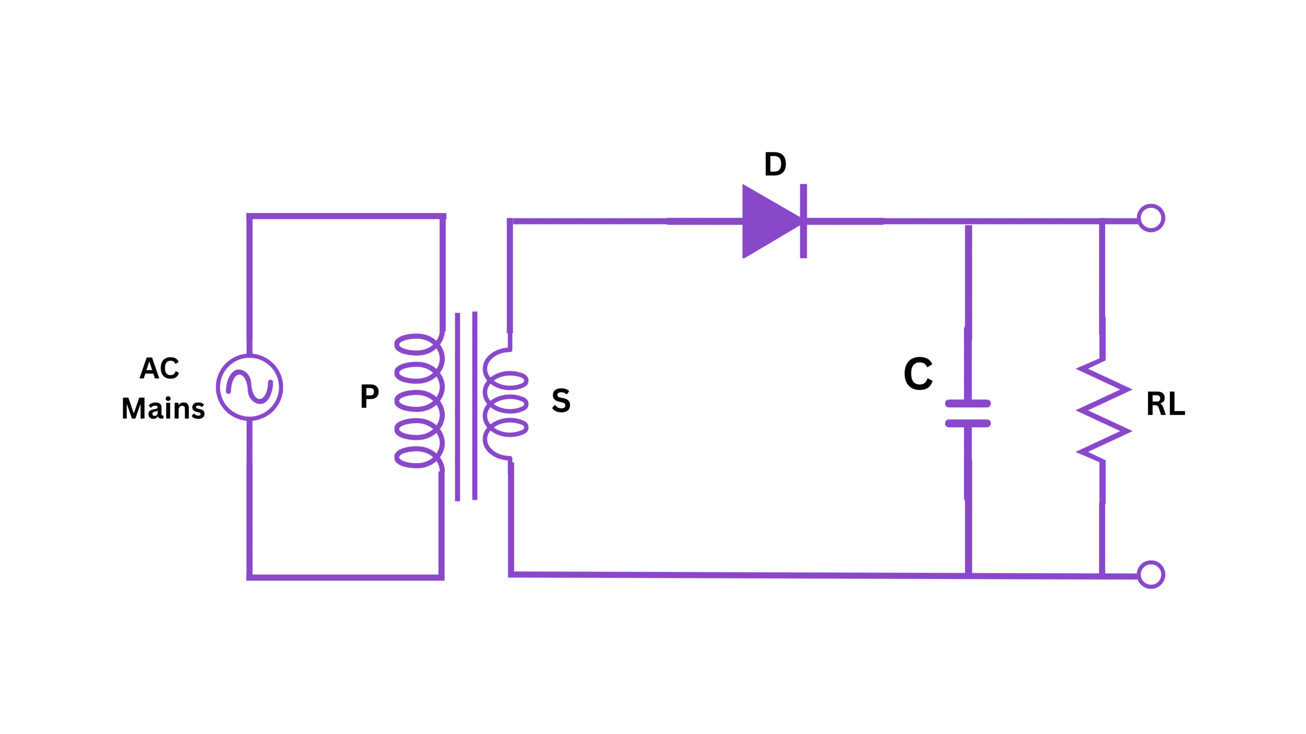
Fig 1: Circuit diagram of Half Wave Rectifier with Capacitive Filter
4. Theory
A half-wave rectifier is a circuit that converts an AC voltage into a DC voltage by allowing current flow only during the positive half-cycle of the input AC voltage while blocking the flow during the negative half-cycle.
The basic half-wave rectifier consists of a single diode that conducts current when it is forward biased (during the positive half-cycle) and blocks current when it is reverse biased (during the negative half-cycle). The output of a basic half-wave rectifier is a pulsating DC with high ripple content.
To smooth this pulsating DC output, a filter capacitor is connected in parallel with the load resistor. This configuration is known as a half-wave rectifier with capacitive filter.
Working Principle:
During the positive half-cycle of the input AC voltage:
- The diode is forward biased and conducts current
- The capacitor charges to the peak value of the input voltage (minus the diode drop)
- Current flows through the load resistor
During the negative half-cycle of the input AC voltage:
- The diode is reverse biased and blocks current
- The capacitor discharges slowly through the load resistor
- The discharging capacitor maintains current flow through the load
This charging and discharging action of the capacitor helps to maintain a more constant voltage across the load, thereby reducing the ripple in the output voltage. The effectiveness of the filter depends on the capacitance value and the load resistance.
The time constant (τ = RC) of the circuit determines how quickly the capacitor discharges. A larger time constant results in slower discharge and hence less ripple in the output voltage.
5. Formulas
Input and Output Relationships:
RMS value of the input voltage: $V_{rms} = \frac{V_m}{\sqrt{2}}$
Average (DC) output voltage without filter: $V_{dc} = \frac{V_m}{\pi} = 0.318 \times V_m$
Average (DC) output voltage with capacitive filter: $V_{dc} = V_m - \frac{V_m}{2fRC}$
Where $V_m$ is the peak input voltage, $f$ is the frequency, $R$ is the load resistance, and $C$ is the filter capacitance.
Ripple Calculations:
Ripple factor without filter: $r = \frac{V_{rms}}{V_{dc}} - 1 = 1.21$
Ripple factor with capacitive filter: $r = \frac{1}{2\sqrt{3}fRC}$
Peak-to-peak ripple voltage: $V_r = \frac{V_m}{fRC}$
Efficiency Calculations:
Rectification efficiency without filter: $\eta = \frac{P_{dc}}{P_{ac}} \times 100\% = 40.6\%$
Rectification efficiency with capacitive filter: $\eta = \frac{P_{dc}}{P_{ac}} \times 100\% = \frac{V_{dc}^2/R}{V_{rms}^2/2R} \times 100\%$
Form Factor:
Form Factor = $\frac{V_{rms}}{V_{dc}}$
Transformer Utilization Factor (TUF):
TUF = $\frac{P_{dc}}{P_t} = 0.406$
Where $P_{dc}$ is the DC power output and $P_t$ is the transformer's VA rating.
6. Procedure
- Connect the circuit as shown in the circuit diagram. Initially, do not connect the filter capacitor.
- Turn on the power supply and set the transformer input to the required voltage (typically 230V AC).
- Using the CRO, observe and record the input AC waveform across the secondary of the transformer.
- Observe and record the output waveform of the half-wave rectifier without the filter.
- Measure and record the following parameters:
- RMS input voltage
- DC output voltage
- Peak output voltage
- Now connect the 10μF capacitor across the load resistor.
- Observe and record the new output waveform on the CRO.
- Measure and record the DC output voltage and the ripple voltage.
- Repeat steps 7 and 8 with different capacitor values (47μF, 100μF, and 1000μF).
- Repeat steps 7 through 9 with a different load resistor value.
- Turn off the power supply and disconnect the circuit.
- Calculate the ripple factor, form factor, and rectification efficiency for each configuration.
- Plot graphs of ripple factor vs. capacitance and DC output voltage vs. capacitance.
7. Observation Table
Table 1: Half-Wave Rectifier without Filter
| Input RMS Voltage (V) |
Input Peak Voltage (V) |
Output DC Voltage (V) |
Output RMS Voltage (V) |
Form Factor | Ripple Factor | Efficiency (%) |
|---|---|---|---|---|---|---|
Table 2: Half-Wave Rectifier with Capacitive Filter (Load Resistance = 1kΩ)
| Capacitance (μF) |
Output DC Voltage (V) |
Ripple Voltage (V) |
Calculated Ripple Factor | Theoretical Ripple Factor | Efficiency (%) |
|---|---|---|---|---|---|
| 10 | |||||
| 47 | |||||
| 100 | |||||
| 1000 |
Table 3: Half-Wave Rectifier with Capacitive Filter (Load Resistance = 10kΩ)
| Capacitance (μF) |
Output DC Voltage (V) |
Ripple Voltage (V) |
Calculated Ripple Factor | Theoretical Ripple Factor | Efficiency (%) |
|---|---|---|---|---|---|
| 10 | |||||
| 47 | |||||
| 100 | |||||
| 1000 |
8. Calculations
Using the formulas given in the theory section, calculate the following parameters:
For Half-Wave Rectifier without Filter:
1. Peak Input Voltage: $V_m = V_{rms} \times \sqrt{2}$
2. Theoretical DC Output Voltage: $V_{dc} = \frac{V_m}{\pi} = 0.318 \times V_m$
3. Form Factor: $\frac{V_{rms}}{V_{dc}}$
4. Ripple Factor: $r = \sqrt{\frac{V_{rms}^2}{V_{dc}^2} - 1}$
5. Rectification Efficiency: $\eta = \frac{V_{dc}^2/R}{V_{rms}^2/2R} \times 100\%$
For Half-Wave Rectifier with Capacitive Filter:
1. Calculated Ripple Factor: $r = \frac{V_r}{V_{dc}}$
2. Theoretical Ripple Factor: $r = \frac{1}{2\sqrt{3}fRC}$
3. Theoretical Ripple Voltage: $V_r = \frac{V_m}{fRC}$
4. Efficiency: $\eta = \frac{V_{dc}^2/R}{V_{rms}^2/2R} \times 100\%$
Sample calculation for one set of readings:
Given:
- Input RMS voltage: ___ V
- Load resistance: ___ kΩ
- Capacitance: ___ μF
- Frequency: 50 Hz
- Measured output DC voltage: ___ V
- Measured ripple voltage: ___ V
The calculations will be filled in based on observed values during the experiment.
9. Result
Based on the observations and calculations, the following results can be concluded:
- The half-wave rectifier without filter produces a pulsating DC output with a high ripple factor of approximately 1.21.
- The addition of a capacitive filter significantly reduces the ripple factor.
- As the capacitance value increases, the ripple factor decreases, and the DC output voltage increases.
- For a given capacitance value, increasing the load resistance results in a lower ripple factor.
- The rectification efficiency of a half-wave rectifier with capacitive filter is higher than that without filter.
- The experimental values of ripple factor closely match with the theoretical values within experimental errors.
- The observed relation between capacitance and ripple factor follows the expected inverse relationship.
The performance characteristics of the half-wave rectifier with capacitive filter have been successfully studied and analyzed.
10. Precautions
- Always ensure that the circuit connections are correct before turning on the power supply.
- Use the correct polarity for diodes and electrolytic capacitors.
- Ensure that the voltage rating of the capacitors is higher than the peak voltage of the circuit.
- Do not touch any part of the circuit when the power supply is on.
- Use proper ground connections for the oscilloscope to avoid electric shock.
- Take readings carefully to minimize errors.
- Ensure that the diode's maximum current rating is not exceeded.
- Make sure the transformer is properly rated for the experiment.
- When using high capacitance values, be aware of the charging current which may be high initially.
- Handle the breadboard and components carefully to avoid damage.
- Turn off the power supply when changing components or connections.
- Keep the circuit area clean and organized to avoid short circuits.
11. Viva Voice Questions
Q1: What is the purpose of a rectifier in electronic circuits?
A rectifier is a device that converts alternating current (AC) to direct current (DC) by allowing current flow in only one direction. It is essential in power supply circuits to convert the available AC supply into DC required by most electronic devices.
Q2: Compare half-wave and full-wave rectifiers.
Half-wave rectifier:
- Uses only one diode
- Utilizes only half of the input cycle
- Has lower DC output voltage
- Has higher ripple factor (1.21)
- Has lower efficiency (40.6%)
- Lower TUF (0.406)
- Uses two or four diodes
- Utilizes both halves of the input cycle
- Has higher DC output voltage
- Has lower ripple factor (0.48)
- Has higher efficiency (81.2%)
- Higher TUF (0.812)
Q3: Why is a filter circuit necessary in a rectifier circuit?
A filter circuit is necessary to smooth out the pulsating DC output from the rectifier into a steady DC voltage with minimal ripple. Without a filter, the large voltage variations would make the rectified output unsuitable for most electronic applications that require a stable DC supply.
Q4: How does a capacitive filter work in a rectifier circuit?
A capacitive filter works on the principle of charging and discharging. During the conduction phase of the diode, the capacitor charges to the peak value of the input voltage. When the diode stops conducting, the capacitor discharges slowly through the load resistor, maintaining current flow during the non-conducting period of the diode. This action reduces the ripple in the output voltage.
Q5: What is ripple factor and how is it calculated?
Ripple factor is a measure of the fluctuation in the output voltage of a rectifier circuit. It is defined as the ratio of the RMS value of the AC component to the DC component in the output. For a half-wave rectifier without filter, the ripple factor is 1.21. With a capacitive filter, it can be calculated as r = 1/(2√3fRC) where f is the frequency, R is the load resistance, and C is the filter capacitance.
Q6: How does the value of filter capacitance affect the ripple factor?
The ripple factor is inversely proportional to the filter capacitance. As the capacitance increases, the ripple factor decreases, resulting in a smoother DC output. This is because a larger capacitor can store more charge and discharge more slowly during the non-conducting period of the diode.
Q7: What happens to the output DC voltage and ripple factor when the load resistance is increased?
When the load resistance is increased:
- The output DC voltage increases slightly because there is less voltage drop across the diode and transformer resistance.
- The ripple factor decreases because the time constant (RC) increases, allowing the capacitor to discharge more slowly.
Q8: What is the PIV (Peak Inverse Voltage) rating of a diode and why is it important in rectifier circuits?
The Peak Inverse Voltage (PIV) rating of a diode is the maximum reverse voltage that a diode can withstand without breakdown. In a half-wave rectifier, the PIV is equal to the peak value of the input voltage. It is important because if the reverse voltage exceeds the PIV rating, the diode may undergo avalanche breakdown and get damaged.
Q9: Why is the efficiency of a half-wave rectifier lower than that of a full-wave rectifier?
The efficiency of a half-wave rectifier is lower because it utilizes only half of the input cycle while blocking the other half. This means that half of the available input power is not used. In contrast, a full-wave rectifier utilizes both halves of the input cycle, resulting in better utilization of the transformer and higher efficiency.
Q10: What is the significance of the time constant (RC) in a capacitive filter circuit?
The time constant (RC) in a capacitive filter circuit determines how quickly the capacitor discharges through the load resistor. A larger time constant means slower discharge and hence less ripple in the output voltage. For effective filtering, the time constant should be much larger than the period of the input AC voltage.