
Full Wave Rectifier with Capacitor Filter Circuit
1. Aim
To study the characteristics of a Full Wave Rectifier circuit with a capacitor filter and observe the effect of the filter on the output waveform.
2. Apparatus Used
- Step-down transformer (center-tapped, 12-0-12V)
- Diodes (1N4007) - 2 nos.
- Capacitor (1000 μF, 25V) - 1 no.
- Resistors (1kΩ) - 1 no.
- CRO (Cathode Ray Oscilloscope)
- Function generator
- Bread board
- Connecting wires
- Digital multimeter
- Regulated power supply (RPS)
3. Diagram
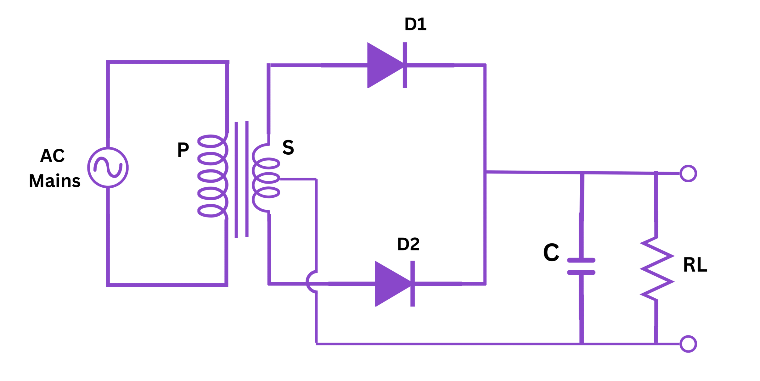
Fig 1: Circuit diagram of Full Wave Rectifier with Capacitor Filter
4. Theory
A full wave rectifier is a circuit that converts alternating current (AC) to direct current (DC) by utilizing both halves of the AC cycle. Unlike a half-wave rectifier which only uses one half of the AC waveform, the full wave rectifier rectifies both positive and negative halves of the input waveform, resulting in a more efficient conversion process.
The full wave rectifier circuit can be constructed using two methods:
- Using a center-tapped transformer with two diodes
- Using a bridge rectifier with four diodes
In this experiment, we will focus on the center-tapped transformer method. The center-tapped transformer provides two equal but opposite voltages with respect to the center tap (ground). During the positive half-cycle of the AC input, one diode conducts while the other is reverse-biased. During the negative half-cycle, the situation is reversed. As a result, the current through the load resistor flows in the same direction during both half-cycles, producing a pulsating DC output.
However, this pulsating DC contains significant ripple content, which is undesirable for most electronic applications. To reduce the ripple voltage and provide a smoother DC output, a filter capacitor is connected across the load resistor. This capacitor charges during the peak of the rectified waveform and discharges slowly through the load resistor when the rectified voltage drops, thus maintaining a more constant voltage level.
The capacitor filter works based on the principle that a capacitor opposes any change in voltage across it. When the rectified voltage is rising, the capacitor charges up to the peak voltage. When the rectified voltage begins to fall, the capacitor discharges slowly through the load resistor, keeping the output voltage relatively constant until the next peak of the rectified waveform.
5. Formula
For Full Wave Rectifier with Capacitor Filter:
1. DC Output Voltage (Average Voltage):
$$V_{DC} = \frac{2V_m}{\pi} \approx 0.637V_m$$
2. With Capacitor Filter:
$$V_{DC} \approx V_m$$
3. RMS Value of Output Voltage:
$$V_{RMS} = \frac{V_m}{\sqrt{2}} \approx 0.707V_m$$
4. Ripple Factor (without filter):
$$r = \frac{V_{ripple(rms)}}{V_{DC}} = \sqrt{\left(\frac{V_{rms}}{V_{DC}}\right)^2 - 1} \approx 0.48$$
5. Ripple Factor (with capacitor filter):
$$r \approx \frac{1}{2\sqrt{3}fCR_L}$$
6. Rectification Efficiency:
$$\eta = \frac{P_{DC}}{P_{AC}} \times 100\% \approx 81.2\%$$
7. Regulation:
$$Regulation = \frac{V_{NL} - V_{FL}}{V_{FL}} \times 100\%$$
Where:
- $V_m$ = Peak voltage of the secondary winding
- $f$ = Frequency of input AC
- $C$ = Filter capacitance
- $R_L$ = Load resistance
- $V_{NL}$ = No-load voltage
- $V_{FL}$ = Full-load voltage
6. Procedure
7. Observation Table
A. Without Capacitor Filter
| S.No. | AC Input Voltage (V) | Peak Output Voltage (V) | DC Output Voltage (V) | RMS Output Voltage (V) | Ripple Factor |
|---|---|---|---|---|---|
| 1 | |||||
| 2 | |||||
| 3 | |||||
| 4 | |||||
| 5 |
B. With Capacitor Filter
| S.No. | AC Input Voltage (V) | Peak Output Voltage (V) | DC Output Voltage (V) | RMS Output Voltage (V) | Ripple Factor |
|---|---|---|---|---|---|
| 1 | |||||
| 2 | |||||
| 3 | |||||
| 4 | |||||
| 5 |
C. Regulation Measurement
| S.No. | Load Resistance (Ω) | No-Load Voltage (V) | Full-Load Voltage (V) | Regulation (%) |
|---|---|---|---|---|
| 1 | ||||
| 2 | ||||
| 3 |
8. Calculations
Based on the observations, calculate the following:
1. Without Capacitor Filter:
DC Output Voltage:
$$V_{DC} = \frac{2V_m}{\pi}$$
RMS Output Voltage:
$$V_{RMS} = \frac{V_m}{\sqrt{2}}$$
Ripple Factor:
$$r = \sqrt{\left(\frac{V_{rms}}{V_{DC}}\right)^2 - 1}$$
2. With Capacitor Filter:
DC Output Voltage:
$$V_{DC} \approx V_m$$
Ripple Voltage:
$$V_{ripple} = \frac{V_m}{fCR_L}$$
Ripple Factor:
$$r = \frac{V_{ripple}}{V_{DC}}$$
3. Regulation:
$$Regulation = \frac{V_{NL} - V_{FL}}{V_{FL}} \times 100\%$$
Sample Calculation Format:
For one set of readings:
- Given:
- Input AC voltage = ___ V
- Peak output voltage (Vm) = ___ V
- Load resistance (RL) = ___ Ω
- Filter capacitance (C) = ___ μF
- Frequency (f) = ___ Hz
- For full wave rectifier without filter:
- DC voltage = (2 × Vm)/π = _____ V
- RMS voltage = Vm/√2 = _____ V
- Ripple factor = √[(Vrms/Vdc)² - 1] = _____
- For full wave rectifier with capacitor filter:
- DC voltage = Vm = _____ V
- Ripple voltage = Vm/(f×C×RL) = _____ V
- Ripple factor = Vripple/Vdc = _____
- Regulation:
- No-load voltage (VNL) = _____ V
- Full-load voltage (VFL) = _____ V
- Regulation = [(VNL - VFL)/VFL] × 100% = _____
9. Result
In this experiment, we have studied the characteristics of a full wave rectifier circuit with and without a capacitor filter. Based on the observations and calculations, we can conclude:
- The full wave rectifier successfully converted AC input to pulsating DC output using both halves of the AC cycle.
- The average DC output voltage of the full wave rectifier without filter was approximately 0.637 times the peak voltage.
- The ripple factor of the full wave rectifier without filter was approximately 0.48.
- When a capacitor filter was added to the circuit, the DC output voltage increased to nearly the peak value.
- The capacitor filter significantly reduced the ripple in the output voltage, making it smoother and more suitable for electronic applications.
- The ripple factor with capacitor filter was found to be much lower than without filter.
- The regulation of the rectifier circuit indicates how the output voltage changes with load.
The practical values obtained in the experiment were found to be in good agreement with the theoretical values, validating the theory and formulas of full wave rectifier with capacitor filter.
10. Precautions
- Ensure proper connections before switching on the power supply.
- Use appropriate range of multimeter for voltage and current measurements.
- Observe the polarity of diodes and capacitors while connecting in the circuit.
- Ensure that the voltage rating of the capacitor is higher than the peak output voltage.
- Do not exceed the maximum ratings of the diodes.
- Turn off the power supply before making any changes in the circuit.
- Properly ground the CRO to avoid electric shock.
- Ensure center tap of the transformer is properly grounded.
- Allow some time for the capacitor to discharge before handling the circuit after power off.
- Avoid touching exposed connections when the circuit is energized.
- Keep the circuit away from water and moisture.
- Handle the CRO with care, as it is a sensitive instrument.
11. Viva Voice Questions
Q1. What is the difference between half wave and full wave rectifier?
A half wave rectifier uses only one half (positive or negative) of the AC input cycle, while a full wave rectifier uses both halves of the input cycle. Full wave rectifier provides better efficiency, lower ripple factor, and higher output voltage compared to a half wave rectifier.
Q2. Why is center-tapped transformer used in a full wave rectifier?
A center-tapped transformer provides two equal but opposite voltages with respect to the center tap, allowing each diode to conduct during alternate half-cycles. This arrangement enables the full wave rectification using only two diodes instead of four diodes as in a bridge rectifier.
Q3. What is ripple factor? Why is it important?
Ripple factor is a measure of the AC component present in the rectified output relative to the DC component. It indicates the effectiveness of the rectification process. A lower ripple factor means a smoother DC output which is desirable for most electronic applications.
Q4. How does a capacitor filter work in a rectifier circuit?
A capacitor filter works on the principle of charging and discharging. It charges to the peak value of the rectified waveform and then discharges slowly through the load when the rectified voltage drops. This helps in maintaining a more constant voltage level across the load, reducing the ripple in the output.
Q5. What factors affect the ripple factor in a capacitor filter circuit?
The ripple factor in a capacitor filter circuit is affected by the capacitance value, load resistance, and frequency of the input signal. A higher capacitance, higher load resistance, or higher frequency will result in a lower ripple factor.
Q6. Compare bridge rectifier with center-tapped full wave rectifier.
The bridge rectifier uses four diodes without a center-tapped transformer, while the center-tapped rectifier uses two diodes with a center-tapped transformer. Bridge rectifier utilizes the full secondary voltage, whereas in center-tapped rectifier, only half of the secondary voltage is utilized at any time. Bridge rectifier has better transformer utilization factor but has two diode voltage drops compared to one in the center-tapped rectifier.
Q7. What is the PIV (Peak Inverse Voltage) rating of diodes in a full wave rectifier?
In a center-tapped full wave rectifier, the PIV rating of each diode should be at least 2Vm, where Vm is the peak voltage of half the secondary winding. This is because when one diode is conducting, the other diode experiences a reverse bias equal to the sum of the forward voltage across the conducting diode and the transformer voltage.
Q8. What is the significance of the form factor in rectifier circuits?
Form factor is the ratio of RMS value to the average value of a waveform. It is a measure of the shape of the waveform. For a full wave rectified output without filter, the form factor is approximately 1.11. A form factor of 1 indicates a pure DC output with no ripple.
Q9. Why is regulation important in power supply circuits?
Regulation is important because it indicates how stable the output voltage remains when the load changes. A good power supply should maintain nearly constant output voltage regardless of the load, which means it should have a low regulation percentage.
Q10. What other types of filters can be used in rectifier circuits besides capacitor filters?
Besides capacitor filters, other types include inductor filters (choke filters), LC filters (capacitor-input or inductor-input), and π-filters (CLC filters). Each has its own advantages in terms of ripple reduction, voltage regulation, and current handling capacity.
For More experiment Manual Click on Link...