
TO STUDY GATE FIRING CIRCUIT FOR SILICON CONTROLLED RECTIFIER
1. AIM
To design, construct, and study the working of a gate firing circuit for Silicon Controlled Rectifier (SCR) and to analyze its triggering characteristics.
2. APPARATUS USED
- Silicon Controlled Rectifier (SCR) - TYN612 or equivalent
- Resistors (1kΩ, 10kΩ, 100Ω, as required)
- Capacitors (10μF, 0.1μF)
- Variable DC power supply (0-30V)
- Oscilloscope (dual channel)
- Function generator
- Multimeter
- Connecting wires
- Breadboard
- Potentiometer (10kΩ)
- Diodes (1N4007)
- Load resistor (100Ω, 5W)
3. DIAGRAM
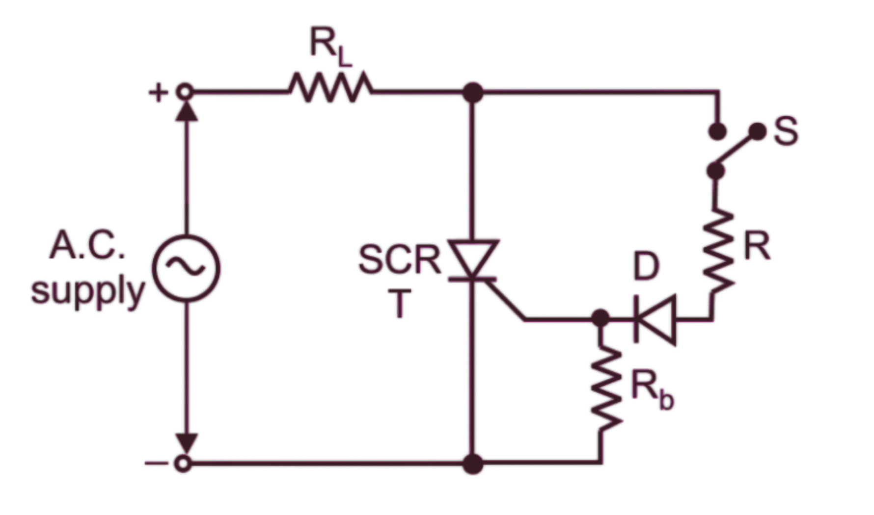
Figure 1: Basic SCR Gate Firing Circuit
4. THEORY
The Silicon Controlled Rectifier (SCR) is a four-layer (P-N-P-N) semiconductor device that acts as a controlled switch. It has three terminals: Anode (A), Cathode (K), and Gate (G). The SCR remains in the OFF state until a trigger pulse is applied to its gate terminal while the device is forward biased.
The gate firing circuit is essential for controlling the SCR's conduction. Once triggered, the SCR continues to conduct even if the gate signal is removed, provided the anode current remains above the holding current. The SCR turns off only when the anode current falls below the holding current or when the device is reverse biased.
Basic Operation:
- Forward Blocking State: When the anode is positive with respect to the cathode, but no gate signal is present, the SCR blocks current flow.
- Forward Conduction State: When a positive gate pulse is applied while the SCR is forward biased, it starts conducting and continues to do so until the anode current falls below the holding current.
Gate Firing Methods:
- DC Gate Triggering: A DC voltage is applied between the gate and cathode.
- AC Gate Triggering: AC voltage is applied to the gate through a resistor.
- Pulse Triggering: Short duration pulses are applied to the gate.
- RC Triggering Circuit: Uses an RC network to control the firing angle.
- UJT Triggering Circuit: Utilizes a UJT relaxation oscillator to generate trigger pulses.
In this experiment, we focus on an RC-based gate firing circuit that allows control of the firing angle by adjusting the RC time constant.
5. FORMULA
The gate current required to trigger the SCR is given by:
$I_G = \frac{V_G - V_{GK}}{R_G}$
Where:
$I_G$ = Gate current
$V_G$ = Gate voltage
$V_{GK}$ = Gate-Cathode forward voltage drop (typically 0.7V)
$R_G$ = Gate resistance
For an RC firing circuit, the firing angle α is related to the RC time constant:
$\alpha = \omega t = \omega RC \ln \left(\frac{V_m}{V_{GT}}\right)$
Where:
$\alpha$ = Firing angle in radians
$\omega$ = Angular frequency (2πf)
$R$ = Resistance in ohms
$C$ = Capacitance in farads
$V_m$ = Peak supply voltage
$V_{GT}$ = Gate trigger voltage
The average output voltage for an SCR with firing angle α is:
$V_{avg} = \frac{V_m}{2\pi}(1 + \cos\alpha)$
Where:
$V_{avg}$ = Average output voltage
$V_m$ = Peak input voltage
$\alpha$ = Firing angle in radians
6. PROCEDURE
- Set up the circuit as shown in the diagram. Use appropriate values for resistors and capacitors.
- Connect the anode of the SCR to the positive terminal of the power supply through a load resistor.
- Connect the cathode of the SCR to the ground (negative terminal of the power supply).
- Set up the gate firing circuit using the RC network and connect it to the gate terminal of the SCR.
- Set the power supply to a suitable voltage (e.g., 12V DC).
- Connect channel 1 of the oscilloscope to measure the voltage across the load resistor.
- Connect channel 2 of the oscilloscope to measure the gate voltage.
- For DC triggering:
- Gradually increase the gate voltage using the potentiometer.
- Note the gate voltage at which the SCR turns ON (observed by voltage drop across the load).
- Measure the corresponding gate current.
- Repeat for different values of gate resistance.
- For RC triggering:
- Connect an AC source to the RC network.
- Vary the resistance value to change the firing angle.
- Observe the waveforms on the oscilloscope.
- Measure the firing angle for different RC combinations.
- To observe the latching action:
- Trigger the SCR with a gate pulse.
- Remove the gate signal and observe that the SCR remains ON.
- Momentarily disconnect the anode supply to turn OFF the SCR.
- Record all observations in the observation table.
- Calculate the gate current, firing angle, and average output voltage using the formulas provided.
7. OBSERVATION TABLE
Table 1: DC Triggering Characteristics
| S.No. | Gate Resistance (Rg) Ω | Gate Voltage (Vg) V | Gate Current (Ig) mA | Anode Voltage (Va) V | Anode Current (Ia) mA | Status of SCR |
|---|---|---|---|---|---|---|
| 1 | ||||||
| 2 | ||||||
| 3 | ||||||
| 4 | ||||||
| 5 |
Table 2: RC Triggering Characteristics
| S.No. | Resistance (R) kΩ | Capacitance (C) μF | RC Time Constant (ms) | Firing Angle (α) degrees | Input Voltage (Vm) V | Average Output Voltage (Vavg) V |
|---|---|---|---|---|---|---|
| 1 | ||||||
| 2 | ||||||
| 3 | ||||||
| 4 | ||||||
| 5 |
8. CALCULATIONS
Sample calculations for one set of readings:
For DC Triggering:
Gate Current calculation:
$I_G = \frac{V_G - V_{GK}}{R_G}$
Example: If $V_G = 1.5V$, $V_{GK} = 0.7V$, and $R_G = 1000\Omega$
$I_G = \frac{1.5 - 0.7}{1000} = \frac{0.8}{1000} = 0.8 \times 10^{-3} = 0.8 mA$
For RC Triggering:
Firing Angle calculation:
$\alpha = \omega RC \ln \left(\frac{V_m}{V_{GT}}\right)$
Example: If $R = 10k\Omega$, $C = 0.1\mu F$, $V_m = 12V$, $V_{GT} = 0.7V$, and $f = 50Hz$
$\omega = 2\pi f = 2\pi \times 50 = 314.16 rad/s$
$\alpha = 314.16 \times 10 \times 10^3 \times 0.1 \times 10^{-6} \times \ln \left(\frac{12}{0.7}\right)$
$\alpha = 314.16 \times 10^{-3} \times \ln(17.14)$
$\alpha = 0.3142 \times 2.84 = 0.892 \text{ rad} = 51.1^{\circ}$
Average Output Voltage calculation:
$V_{avg} = \frac{V_m}{2\pi}(1 + \cos\alpha)$
Using the above example with $\alpha = 51.1^{\circ} = 0.892 \text{ rad}$ and $V_m = 12V$:
$V_{avg} = \frac{12}{2\pi}(1 + \cos(0.892))$
$V_{avg} = \frac{12}{6.28}(1 + 0.623)$
$V_{avg} = 1.91 \times 1.623 = 3.1 V$
9. RESULT
- The gate firing circuit for the Silicon Controlled Rectifier was successfully designed and tested.
- The minimum gate voltage required to trigger the SCR was found to be ________ V.
- The minimum gate current required to trigger the SCR was found to be ________ mA.
- The relationship between the RC time constant and firing angle was observed and verified.
- The effect of varying the firing angle on the average output voltage was studied.
- The latching characteristic of the SCR was demonstrated successfully.
10. PRECAUTIONS
- Ensure that the SCR's maximum ratings (voltage, current, power) are not exceeded.
- Always connect a current-limiting resistor in series with the gate to protect it from excessive current.
- Use a proper heat sink for the SCR if operating at high power levels.
- Avoid connecting or disconnecting components while the circuit is powered on.
- Ensure proper isolation between the control circuit and the power circuit.
- Turn off the power supply before making any changes to the circuit connections.
- Be careful with the oscilloscope probe connections to avoid short circuits.
- Verify that all connections are correct before applying power to the circuit.
- When measuring high voltages, use appropriate probes and take necessary safety precautions.
- Ensure proper grounding of the oscilloscope and other measuring equipment.