
DETERMINATION OF CAPACITANCE BY LEAKAGE METHOD
1. AIM
To determine the capacitance of a given Capacitor using the leakage method.
2. APPARATUS USED
- Capacitor of unknown capacitance
- High resistance voltmeter (electrostatic voltmeter)
- Battery or DC power supply (100V)
- Charging key (K₁)
- Discharging key (K₂)
- Stop watch or timer with seconds precision
- Connecting wires
- Insulating stand for the capacitor
3. DIAGRAM
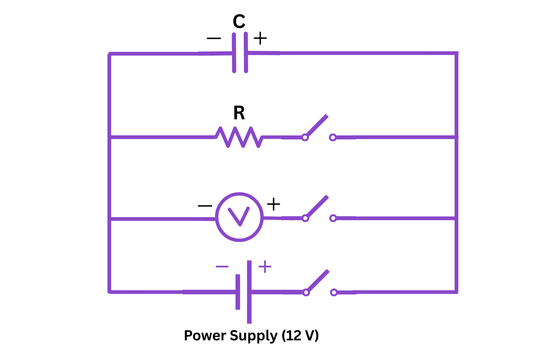
Fig. 1: Circuit diagram for the determination of capacitance using leakage method
4. THEORY
The leakage method for determining capacitance is based on the principle that when a charged capacitor is left isolated, it gradually loses its charge due to the leakage through the dielectric or across the surface of the capacitor. This leakage current can be modeled as a high-value resistor connected in parallel with the capacitor.
When a capacitor is charged to a potential difference V₀ and then left isolated, the voltage across its terminals decays exponentially with time according to the equation:
$$V = V_0 e^{-\frac{t}{RC}}$$
Where:
- V is the voltage across the capacitor at time t
- V₀ is the initial voltage to which the capacitor was charged
- R is the equivalent leakage resistance
- C is the capacitance of the capacitor
- t is the time elapsed since the capacitor was isolated
Taking the natural logarithm of both sides:
$$\ln\left(\frac{V}{V_0}\right) = -\frac{t}{RC}$$
This equation represents a straight line when ln(V/V₀) is plotted against t, with a slope of -1/RC. By measuring the voltage across the capacitor at different times and plotting the natural logarithm of the voltage ratio against time, we can determine the time constant RC of the circuit. If the leakage resistance R is known, the capacitance C can be calculated.
In practice, if the leakage resistance is very high (which is often the case for good capacitors), we can use an approximation. For small discharge times compared to the time constant RC:
$$C = \frac{(V_0 - V)t}{RV_0}$$
5. FORMULA
From the theory, the capacitance can be determined using the following formula:
$$C = \frac{-t}{R \ln\left(\frac{V}{V_0}\right)}$$
Where:
- C is the capacitance in farads (F)
- R is the leakage resistance in ohms (Ω)
- V₀ is the initial voltage in volts (V)
- V is the voltage after time t in volts (V)
- t is the time in seconds (s)
If we observe voltage readings at equal time intervals, we can also use:
$$C = \frac{0.4343 \times t}{R \times \log_{10}\left(\frac{V_1}{V_2}\right)}$$
Where V₁ and V₂ are voltages at two different times separated by time interval t.
6. PROCEDURE
- Set up the circuit as shown in the diagram. The capacitor is initially uncharged.
- Close key K₁ while keeping key K₂ open. This will charge the capacitor to the battery voltage V₀.
- Note the initial reading V₀ on the voltmeter.
- Open key K₁ to isolate the charged capacitor (leaving K₂ open).
- Start the stopwatch immediately after opening K₁.
- Record the voltage across the capacitor at regular time intervals (e.g., every 30 seconds) for about 10 minutes or until the voltage has decreased significantly.
- After completing the readings, close key K₂ to discharge the capacitor completely.
- Repeat the experiment at least three times for consistency.
- Calculate the natural logarithm of the ratio V/V₀ for each time reading.
- Plot a graph of ln(V/V₀) against time t.
- Determine the slope of the graph, which equals -1/RC.
- Calculate the capacitance using the known value of the leakage resistance R.
7. OBSERVATION TABLE
Initial voltage V₀ = ________ volts
Leakage resistance R = ________ ohms
| S.No. | Time t (seconds) | Voltage V (volts) | V/V₀ | ln(V/V₀) |
|---|---|---|---|---|
| 1 | 0 | V₀ = | 1.000 | 0.000 |
| 2 | ||||
| 3 | ||||
| 4 | ||||
| 5 | ||||
| 6 | ||||
| 7 | ||||
| 8 |
8. CALCULATIONS
From the graph of ln(V/V₀) against time t:
Slope of the graph = ________
The slope is equal to -1/RC, therefore:
$$-\frac{1}{RC} = \text{Slope}$$
$$C = \frac{-1}{R \times \text{Slope}}$$
Substituting the values:
$$C = \frac{-1}{(\_\_\_\_\_\_\_ \Omega) \times (\_\_\_\_\_\_\_)}$$
$$C = \_\_\_\_\_\_\_ \text{ farads}$$
Convert the result to appropriate units (μF or pF):
$$C = \_\_\_\_\_\_\_ \mu\text{F}$$
9. RESULT
The capacitance of the given capacitor determined by the leakage method is ________ μF.
The percentage error in the measurement can be calculated as:
$$\text{Percentage Error} = \frac{|\text{Measured Value} - \text{True Value}|}{\text{True Value}} \times 100\%$$
If the true value is known: Percentage Error = ________%
10. PRECAUTIONS
- Ensure that the capacitor is completely discharged before starting the experiment.
- The voltmeter used should have a very high input impedance to minimize its loading effect on the circuit.
- Avoid touching the capacitor terminals during the experiment to prevent additional leakage paths.
- Keep the capacitor and circuit components on an insulating stand to minimize leakage to ground.
- Ensure good insulation in all connections and minimize contact resistance.
- The environment should be dry to prevent humidity-related leakage effects.
- Temperature should be kept constant throughout the experiment, as temperature variations can affect leakage resistance.
- Take readings at regular intervals and be precise with the timing.
- When dealing with high voltages, ensure proper safety measures are followed.
- Repeat the experiment multiple times for more accurate results.