
STUDY OF OPERATIONAL AMPLIFIER AS SUBTRACTOR
1. AIM
To design, setup, and verify the operation of an Operational Amplifier (OP AMP) based subtractor circuit, and to study its characteristics and applications.
2. APPARATUS USED
- Operational Amplifier IC 741 (1 no.)
- Resistors: 10kΩ (4 nos.)
- Dual Power Supply (±15V)
- Digital Multimeter (2 nos.)
- Breadboard
- Connecting wires
- Function Generator
- Oscilloscope (Optional, for waveform analysis)
- Digital DC Voltmeter
3. DIAGRAM
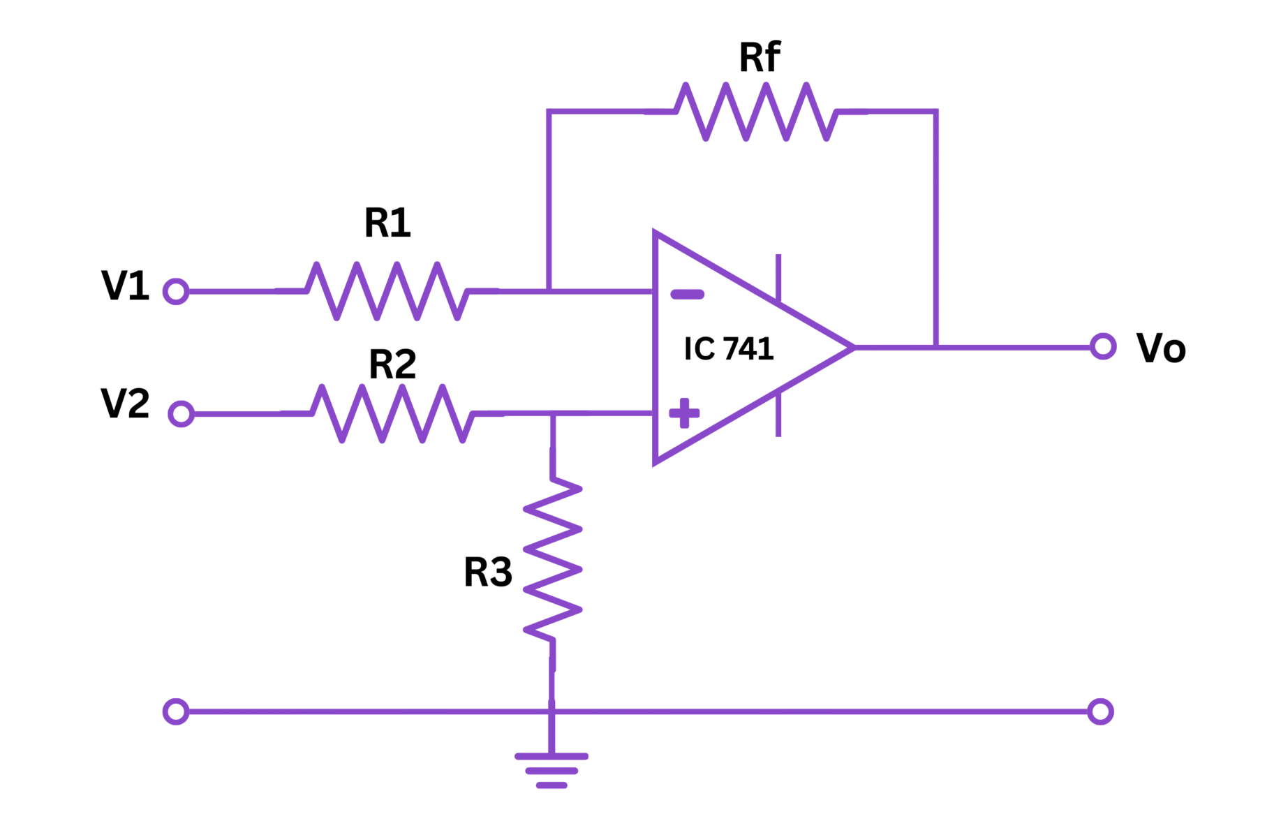
Fig 1: Circuit diagram of OP AMP subtractor
4. THEORY
An operational amplifier (OP AMP) is a high gain electronic voltage amplifier with a differential input and typically a single-ended output. One of the many applications of an OP AMP is as a subtractor (also called a difference amplifier).
A subtractor is an electronic circuit that produces an output voltage equal to the difference between two input voltages, multiplied by a constant gain factor. The subtractor circuit uses a combination of inverting and non-inverting amplifier principles.
In the basic subtractor configuration:
- The differential input (between the inverting and non-inverting terminals) is amplified
- Equal resistors ensure unity gain for simple subtraction
- Different resistor values can provide scaling of the subtracted result
The subtractor circuit works on the principle of superposition. The output is influenced by both inputs: $V_1$ (applied to non-inverting terminal through a voltage divider) and $V_2$ (applied to the inverting terminal).
When all resistors are of equal value (R), the output is simply proportional to the difference between the two inputs ($V_1 - V_2$).
In the general case with potentially different resistor values, the output can be calculated using the transfer function derived from nodal analysis of the circuit.
5. FORMULA
For the general case of a subtractor with resistors $R_1$, $R_2$, $R_3$, and $R_4$:
$$V_{out} = \frac{R_2}{R_1} \left( \frac{R_3}{R_3 + R_4} V_1 - V_2 \right)$$
When $\frac{R_2}{R_1} = \frac{R_4}{R_3}$, the formula simplifies to:
$$V_{out} = \frac{R_2}{R_1}(V_1 - V_2)$$
For the special case where all resistors are equal ($R_1 = R_2 = R_3 = R_4 = R$):
$$V_{out} = V_1 - V_2$$
6. PROCEDURE
- Connect the circuit as shown in the diagram using the OP AMP IC 741 and four 10kΩ resistors.
- Apply ±15V DC power supply to the IC at pins 7 (+VCC) and 4 (-VEE).
- Apply input voltage V₁ to the non-inverting terminal (pin 3) through resistor network as shown.
- Apply input voltage V₂ to the inverting terminal (pin 2) through the resistor as shown.
- Measure the input voltages V₁ and V₂ using digital multimeters.
- Measure the output voltage Vout at pin 6 using a digital voltmeter.
- Vary the input voltage V₁ while keeping V₂ constant, and record the readings.
- Next, keep V₁ constant and vary V₂, recording the readings.
- Finally, vary both V₁ and V₂ and record the corresponding output voltages.
- Verify that the output voltage is proportional to the difference between V₁ and V₂.
- Compare theoretical values (calculated) with experimental values to determine the accuracy of the circuit.
7. OBSERVATION TABLE
| S. No. | Input Voltage V₁ (V) | Input Voltage V₂ (V) | Theoretical Output Voltage Vout = V₁ - V₂ (V) | Measured Output Voltage Vout (V) | Error (%) |
|---|---|---|---|---|---|
| 1 | |||||
| 2 | |||||
| 3 | |||||
| 4 | |||||
| 5 | |||||
| 6 | |||||
| 7 | |||||
| 8 |
8. CALCULATIONS
For each set of observations:
- Calculate the theoretical output voltage using the formula:
$V_{out} = V_1 - V_2$(Assuming all resistors are of equal value 10kΩ)
- Calculate the percentage error for each reading:
$\text{Error (\%)} = \left|\frac{V_{out(theoretical)} - V_{out(measured)}}{V_{out(theoretical)}}\right| \times 100\%$
- Calculate the average percentage error:
$\text{Average Error (\%)} = \frac{\sum \text{Error (\%)}}{n}$where n is the number of observations.
Sample calculation for a single reading:
If V₁ = 5V, V₂ = 2V
Theoretical output: Vout = V₁ - V₂ = 5V - 2V = 3V
If measured output is 2.95V
Error (%) = |((3 - 2.95)/3)| × 100% = |(0.05/3)| × 100% = 1.67%
9. RESULT
- The OP AMP subtractor circuit was successfully designed and tested.
- The output voltage of the subtractor was verified to be proportional to the difference between the two input voltages.
- The average percentage error in measurements was found to be ____% (to be filled after experiment).
- The circuit demonstrated good linearity over the input voltage range tested.
- The experimental results closely matched the theoretical predictions, confirming the operation of the OP AMP as a subtractor.
10. PRECAUTIONS
- Ensure proper connections and polarities of the power supply to avoid damage to the OP AMP.
- Use resistors with tolerance ±1% for better accuracy.
- Keep input voltages within the specified limits of the OP AMP (typically ±13.5V for ±15V supply).
- Avoid touching the circuit components while the power is on.
- Verify that the OP AMP is not oscillating due to improper connections or power supply issues.
- Use shielded cables for measurements to minimize noise.
- Ensure that the breadboard connections are secure and proper.
- Wait for the circuit to stabilize before taking readings.
- Make sure the OP AMP is not in saturation region while taking measurements.
- Check for ground loops and eliminate them if present.