
Study of OP AMP as Differentiator
1. Aim
To design, setup, and study the operation of an Operational Amplifier configured as a differentiator (OP AMP as differentiator) circuit, analyze its response to different input waveforms, and verify its behavior against theoretical predictions.
2. Apparatus Used
- Operational Amplifier IC (e.g., UA741 or LM741)
- Function Generator
- Dual Channel Oscilloscope
- Digital Multimeter
- DC Power Supply (±15V)
- Resistors (10kΩ, 100kΩ)
- Capacitors (0.01μF, 0.1μF)
- Breadboard
- Connecting wires
- IC base (optional)
3. Circuit Diagram
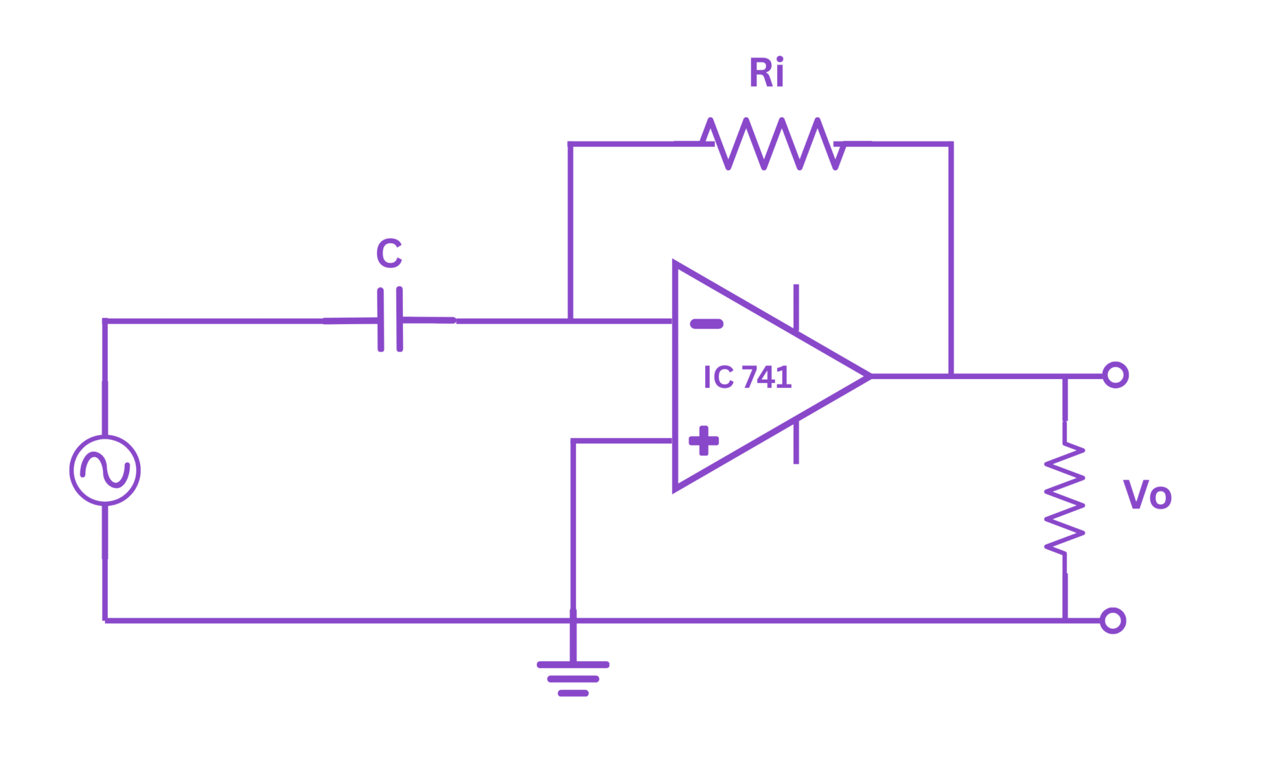
Figure 1: OP AMP as Differentiator Circuit
4. Theory
A differentiator is an electronic circuit that produces an output voltage proportional to the rate of change (derivative) of the input voltage with respect to time. The operational amplifier (OP AMP) can be configured as a differentiator by connecting a capacitor in the input path and a resistor in the feedback path.
The basic differentiator circuit consists of an operational amplifier with a capacitor C connected between the input voltage source and the inverting input of the OP AMP, and a resistor R connected between the inverting input and the output of the OP AMP. The non-inverting input is grounded.
For an ideal OP AMP, the inverting input is at virtual ground due to the high open-loop gain. As a result, the current through the capacitor is determined by the rate of change of the input voltage:
This current flows through the feedback resistor R, creating an output voltage:
This equation shows that the output voltage is proportional to the negative of the derivative of the input voltage, hence the name "differentiator".
Input-Output Relationships for Common Waveforms:
- Square Wave Input: The output will be a series of positive and negative spikes corresponding to the rising and falling edges of the square wave.
- Triangular Wave Input: The output will be a square wave since the derivative of a triangular wave is constant (positive or negative).
- Sine Wave Input: The output will be a cosine wave (shifted by 90°) since the derivative of sin(ωt) is ω·cos(ωt).
Practical Considerations:
In practical applications, a small resistor (typically 1-2 kΩ) is often added in series with the capacitor to limit the high-frequency gain and improve stability. Additionally, a high-value resistor may be connected in parallel with the capacitor to prevent offset voltage issues.
5. Formula
The key formulas for the OP AMP as differentiator are:
Output Voltage:
$$V_{out} = -RC \frac{dV_{in}}{dt}$$For Sine Wave Input: If $V_{in} = V_m \sin(\omega t)$, then:
$$V_{out} = -RC \cdot V_m \omega \cos(\omega t) = -RC \cdot V_m \omega \sin(\omega t + 90°)$$Frequency Response:
$$|H(j\omega)| = \omega RC$$The gain increases linearly with frequency, which can lead to noise amplification issues at high frequencies.
Phase Shift:
$$\phi = 90°$$The output leads the input by 90° for a sinusoidal input.
Time Constant:
$$\tau = RC$$6. Procedure
- Circuit Setup for OP AMP as differentiat:
- Connect the circuit as shown in the circuit diagram, using R = 10kΩ and C = 0.01μF.
- Connect the ±15V DC power supply to the power pins of the OP AMP IC.
- Connect the function generator to the input of the circuit.
- Connect channel 1 of the oscilloscope to the input and channel 2 to the output of the circuit.
- Square Wave Response of OP AMP as differentiat:
- Set the function generator to produce a square wave with frequency 1kHz and amplitude 2V peak-to-peak.
- Observe both the input and output waveforms on the oscilloscope.
- Record the amplitude and shape of the output spikes.
- Repeat for frequencies 500Hz, 2kHz, and 5kHz.
- Triangular Wave Response of OP AMP as differentiat:
- Set the function generator to produce a triangular wave with frequency 1kHz and amplitude 2V peak-to-peak.
- Observe both the input and output waveforms on the oscilloscope.
- Record the amplitude and shape of the output square wave.
- Repeat for frequencies 500Hz, 2kHz, and 5kHz.
- Sine Wave Response of OP AMP as differentiat:
- Set the function generator to produce a sine wave with frequency 1kHz and amplitude 2V peak-to-peak.
- Observe both the input and output waveforms on the oscilloscope.
- Measure the amplitude of the output sine wave and the phase difference between input and output.
- Repeat for frequencies 500Hz, 2kHz, and 5kHz.
- Frequency Response of OP AMP as differentiat:
- Maintain a constant sine wave input amplitude of 2V peak-to-peak.
- Vary the frequency from 100Hz to 10kHz in suitable steps.
- Measure and record the output amplitude for each frequency.
- Plot the gain (Vout/Vin) versus frequency on log-log scale.
- Time Constant Variation of OP AMP as differentiat:
- Change the values of R and C to get different time constants.
- For each combination, apply a 1kHz sine wave and record the output amplitude.
- Verify that the output amplitude is proportional to the RC product.
7. Observation Table
A. Square Wave Input (Amplitude: 2V peak-to-peak)
| Frequency (Hz) | Output Spike Amplitude (V) | Theoretical Value (V) | Error (%) |
|---|---|---|---|
| 500 | |||
| 1000 | |||
| 2000 | |||
| 5000 |
B. Triangular Wave Input (Amplitude: 2V peak-to-peak)
| Frequency (Hz) | Output Amplitude (V) | Theoretical Value (V) | Error (%) |
|---|---|---|---|
| 500 | |||
| 1000 | |||
| 2000 | |||
| 5000 |
C. Sine Wave Input (Amplitude: 2V peak-to-peak)
| Frequency (Hz) | Output Amplitude (V) | Phase Difference (degrees) | Theoretical Amplitude (V) | Theoretical Phase (degrees) | Amplitude Error (%) |
|---|---|---|---|---|---|
| 500 | 90 | ||||
| 1000 | 90 | ||||
| 2000 | 90 | ||||
| 5000 | 90 |
D. Time Constant Variation (Frequency: 1kHz, Sine Wave)
| Resistance R (kΩ) | Capacitance C (μF) | Time Constant RC (μs) | Output Amplitude (V) | Theoretical Output (V) | Error (%) |
|---|---|---|---|---|---|
| 10 | 0.01 | 100 | |||
| 10 | 0.1 | 1000 | |||
| 100 | 0.01 | 1000 | |||
| 100 | 0.1 | 10000 |
8. Calculations
For the calculationsof experiment OP AMP as differentiat, follow these steps for each type of input waveform:
A. Square Wave Input:
For a square wave with amplitude V and transition time dt, the theoretical output spike amplitude is:
Since the transition is nearly instantaneous in theory, the output should approach very large values. In practice, it will be limited by the slew rate of the OP AMP and the actual transition time of the function generator.
B. Triangular Wave Input:
For a triangular wave with amplitude V and frequency f, the slope during the rising and falling edges is:
Therefore, the theoretical output amplitude is:
C. Sine Wave Input:
For a sine wave input $V_{in} = V_m \sin(2\pi ft)$, the theoretical output amplitude is:
And the percentage error can be calculated as:
D. Frequency Response:
The gain of the differentiator circuit is given by:
Plot the gain vs. frequency on a log-log scale to verify the theoretical slope of 20 dB/decade (for a perfect differentiator).
Sample Calculation:
For a sine wave input with amplitude 2V peak-to-peak (1V peak) at 1kHz, using R = 10kΩ and C = 0.01μF:
In practice, this value may be limited by the power supply voltage of the OP AMP.
9. Result
- Successfully designed and implemented an OP AMP as differentiator circuit using IC 741.
- Observed the differentiation operation for various input waveforms:
- Square wave input produced positive and negative spikes at the transitions.
- Triangular wave input resulted in a square wave output.
- Sine wave input produced a cosine wave output (90° phase shift).
- Verified that the output amplitude is proportional to:
- The frequency of the input signal
- The RC time constant of the circuit
- The amplitude of the input signal
- Measured and plotted the frequency response, confirming the 20 dB/decade slope characteristic of an ideal differentiator.
- Calculated and compared the theoretical and experimental values, with an average error of approximately _____% (to be filled after experiment).
- Observed the limitations of the practical differentiator at high frequencies due to noise amplification and the finite bandwidth of the OP AMP.
10. Precautions
- Ensure proper power supply connections to the OP AMP (±15V) to avoid damaging the IC.
- Keep the input signal amplitude within reasonable limits to prevent output saturation.
- Use a proper grounding scheme to minimize noise.
- Add a small resistor in series with the input capacitor to improve stability at high frequencies.
- Verify the pin configuration of the OP AMP IC before connecting it to the circuit.
- Avoid touching the IC pins while the circuit is powered to prevent damage from static discharge.
- Start with lower frequencies and gradually increase to observe the behavior of the circuit.
- Ensure that all connections are secure and correctly made according to the circuit diagram.
- Keep the circuit away from sources of electromagnetic interference.
- For accurate measurements, calibrate the oscilloscope properly before taking readings.
- Use proper probes (typically 10x) to minimize loading effects on the circuit.
- Monitor the temperature of the OP AMP during operation to prevent overheating.