
Determination of Capacitance by de-Sauty's Bridge
1. AIM
To determine the unknown capacitance of a given condenser (capacitor) by using de-Sauty's bridge method.
2. APPARATUS USED
- Standard capacitor (known capacitance)
- Unknown capacitor (to be measured)
- Non-inductive variable resistances (resistance boxes)
- Galvanometer
- High frequency AC source (audio oscillator or buzzer)
- SPDT switch
- Connecting wires
- Headphones (alternative to galvanometer)
3. DIAGRAM
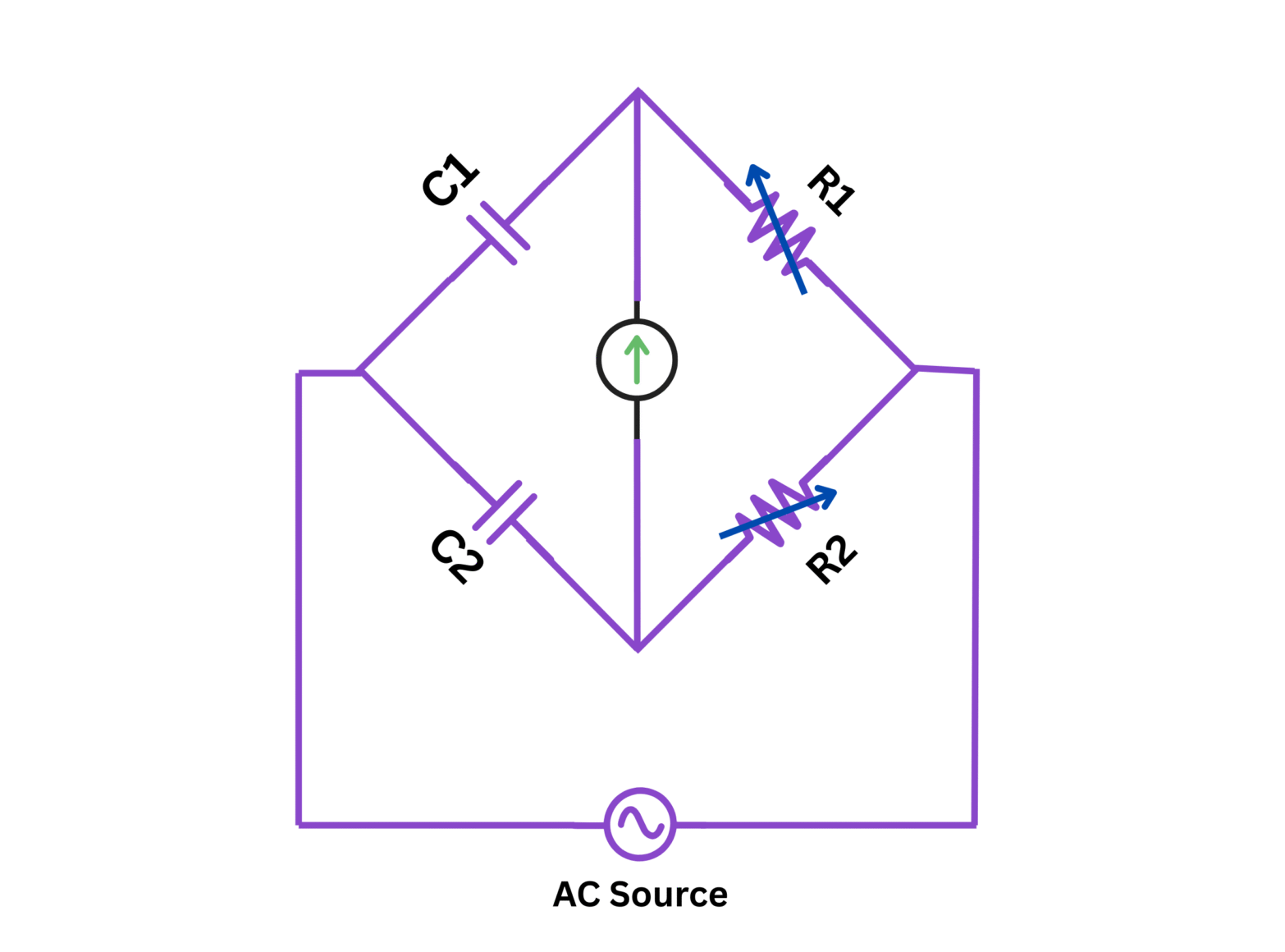
Figure 1: Circuit diagram of de-Sauty's Bridge for capacitance measurement
4. THEORY
De-Sauty's bridge is an AC bridge circuit used to compare and measure unknown capacitance in terms of a standard capacitance. The bridge operates on the principle similar to Wheatstone bridge, but adapted for impedance measurements with capacitances.
In this bridge circuit, the four arms consist of:
- First arm: Standard capacitor with known capacitance $C_s$
- Second arm: Unknown capacitor with capacitance $C_x$ (to be determined)
- Third arm: Non-inductive resistance $R_1$
- Fourth arm: Non-inductive resistance $R_2$
When an AC source is connected across the bridge and the detector (galvanometer or headphones) shows null deflection or minimum sound, the bridge is said to be balanced.
At balance condition, the impedances of the four arms satisfy the relationship:
$\dfrac{Z_1}{Z_2} = \dfrac{Z_3}{Z_4}$
The impedance of a capacitor C with an AC voltage of angular frequency $\omega$ is given by:
$Z = \dfrac{1}{j\omega C}$
Substituting the impedances in the balance equation:
$\dfrac{R_1}{R_2} = \dfrac{\dfrac{1}{j\omega C_s}}{\dfrac{1}{j\omega C_x}} = \dfrac{C_x}{C_s}$
Therefore, at balance condition:
$\dfrac{R_1}{R_2} = \dfrac{C_x}{C_s}$
This allows us to determine the unknown capacitance $C_x$ when the bridge is balanced.
5. FORMULA
From the balanced condition of the de-Sauty's bridge, we have:
$C_x = C_s \times \dfrac{R_2}{R_1}$
Where:
- $C_x$ = Unknown capacitance to be determined (in Farad)
- $C_s$ = Standard capacitance (in Farad)
- $R_1$ = Resistance in the arm with the standard capacitor (in Ohm)
- $R_2$ = Resistance in the arm with the unknown capacitor (in Ohm)
6. PROCEDURE
- Set up the circuit as shown in the circuit diagram of the de-Sauty's bridge.
- Connect the standard capacitor $C_s$ and unknown capacitor $C_x$ in their respective arms of the bridge.
- Connect the AC source (audio oscillator) across points A and C of the bridge.
- Connect the detector (galvanometer or headphones) across points B and D.
- Set initial values for the resistances $R_1$ and $R_2$ (e.g., $R_1 = 1000$ Ω).
- Switch on the AC source.
- Adjust the resistance $R_2$ until the galvanometer shows null deflection (or minimum sound in headphones).
- If null deflection cannot be achieved by adjusting $R_2$ alone, adjust both $R_1$ and $R_2$ alternately.
- When the bridge is balanced (null deflection), note down the values of $R_1$, $R_2$, and $C_s$.
- Repeat the experiment for at least 5 different sets of balanced values of $R_1$ and $R_2$.
- Calculate the unknown capacitance $C_x$ for each set using the formula $C_x = C_s \times \dfrac{R_2}{R_1}$.
- Find the mean value of the unknown capacitance $C_x$.
7. OBSERVATION TABLE
Value of standard capacitance, $C_s$ = ............. µF
| S.No. | Resistance $R_1$ (Ω) | Resistance $R_2$ (Ω) | Ratio $\frac{R_2}{R_1}$ | Unknown Capacitance $C_x = C_s \times \frac{R_2}{R_1}$ (µF) |
|---|---|---|---|---|
| 1 | ||||
| 2 | ||||
| 3 | ||||
| 4 | ||||
| 5 | ||||
| Mean value of unknown capacitance $C_x$ | ||||
8. CALCULATIONS
For each observation, calculate:
1. The ratio $\frac{R_2}{R_1}$
2. The unknown capacitance using the formula:
$C_x = C_s \times \dfrac{R_2}{R_1}$
Example calculation for the first observation:
Given,
- Standard capacitance, $C_s$ = ............. µF
- Resistance $R_1$ = ............. Ω
- Resistance $R_2$ = ............. Ω
Ratio $\frac{R_2}{R_1}$ = $\frac{R_2 \text{ value}}{R_1 \text{ value}}$ = .............
Unknown capacitance, $C_x = C_s \times \frac{R_2}{R_1}$ = ............. × ............. = ............. µF
3. Calculate the mean value of unknown capacitance:
$C_x (mean) = \frac{C_{x1} + C_{x2} + C_{x3} + C_{x4} + C_{x5}}{5}$
4. Calculate the percentage error:
Percentage Error = $\left| \frac{C_x (accepted) - C_x (measured)}{C_x (accepted)} \right| \times 100\%$
Where $C_x (accepted)$ is the value given by the manufacturer or instructor (if available).
9. RESULT
The capacitance of the unknown capacitor measured using de-Sauty's bridge is ............. µF.
If a standard value is available for comparison:
The percentage error in measurement is ............. %.
10. PRECAUTIONS
- All connections should be clean, tight, and properly insulated to avoid contact resistance and leakage currents.
- Use high-quality, non-inductive resistors for $R_1$ and $R_2$ to get accurate results.
- The capacitors should be of good quality with minimal leakage currents.
- Use a stable AC source with appropriate frequency (usually 500-1000 Hz).
- Ensure that the galvanometer or headphones are sensitive enough to detect the null point accurately.
- Keep the bridge and components away from external electromagnetic fields to avoid interference.
- The standard capacitor should be calibrated and its value known precisely.
- For better accuracy, take multiple readings and calculate the average.
- Ensure that the capacitors are fully discharged before connecting or disconnecting them from the circuit.
- Handle the capacitors carefully to avoid damage and ensure accurate measurements.
11. VIVA VOICE QUESTIONS
Q1. What is de-Sauty's bridge and what is its principle?
A1. De-Sauty's bridge is an AC bridge used to measure unknown capacitance by comparing it with a standard capacitance. It works on the principle that when the bridge is balanced, the ratio of resistances equals the inverse ratio of capacitances in the respective arms.
Q2. Why is an AC source used in de-Sauty's bridge instead of DC?
A2. An AC source is used because capacitors block DC current but allow AC current to flow through them due to the property of capacitive reactance. DC would make it impossible to achieve balance in the bridge circuit containing capacitors.
Q3. What is the significance of the null point in the bridge?
A3. The null point indicates that the bridge is balanced, meaning the potential difference across the detector is zero. At this point, the ratio of resistances equals the inverse ratio of capacitances, allowing us to calculate the unknown capacitance.
Q4. How does frequency of the AC source affect the measurement in de-Sauty's bridge?
A4. Ideally, the frequency should not affect the measurement if the capacitors are pure (no losses). However, in practice, capacitors have some dielectric losses that can vary with frequency. Also, if the components have inductive effects, frequency can influence the balance condition. A mid-range frequency (500-1000 Hz) is typically used for optimal results.
Q5. What are the limitations of de-Sauty's bridge?
A5. The limitations include:
- It doesn't account for dielectric losses in capacitors
- It's not suitable for very small or very large capacitances
- Stray capacitances can affect accuracy
- It assumes ideal components with no inductance
- It neglects the equivalent series resistance of capacitors
Q6. What modifications can be made to de-Sauty's bridge to account for losses in capacitors?
A6. To account for losses, the bridge can be modified into a Maxwell bridge or Schering bridge, which include additional resistors or capacitors in parallel or series with the capacitors to balance both the capacitive and resistive components.
Q7. What is the difference between de-Sauty's bridge and Wheatstone bridge?
A7. The Wheatstone bridge is used for measuring unknown resistance by comparing it with a standard resistance using DC, while de-Sauty's bridge is used for measuring unknown capacitance by comparing it with a standard capacitance using AC. The basic principle of balance is similar, but the components and nature of the current differ.
Q8. Why are non-inductive resistors used in the bridge?
A8. Non-inductive resistors are used to ensure that the arms of the bridge have purely resistive behavior without any inductive reactance. This prevents additional phase shifts that would complicate the balance condition and introduce errors in measurements.
Q9. What happens to the balance condition if capacitors have significant leakage current?
A9. Leakage current in capacitors is equivalent to having a high-value resistor in parallel with the capacitor. This adds a resistive component to the impedance, which disturbs the pure capacitive balance condition. It becomes difficult to achieve a sharp null point, and the calculated capacitance will have errors.
Q10. How can you improve the sensitivity of the null detection in de-Sauty's bridge?
A10. The sensitivity can be improved by:
- Using a more sensitive detector (galvanometer or headphones)
- Increasing the voltage of the AC source (within safe limits)
- Using a Wagner earth connection to eliminate stray capacitances
- Employing a lock-in amplifier for detection
- Using shielded cables and proper grounding to reduce noise