
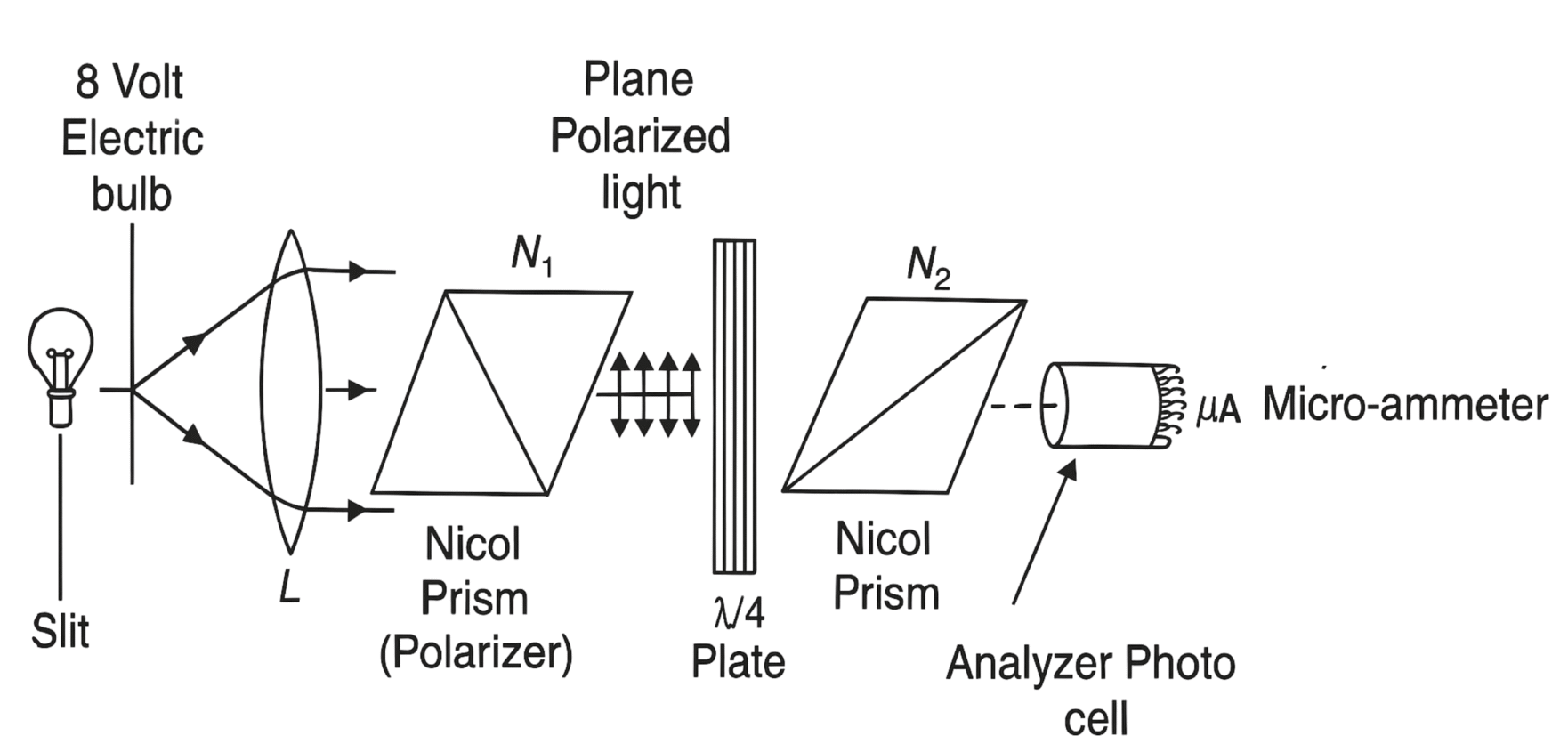
Fig. 1: Experimental setup showing laser source, quarter wave plate, rotating polarizer (analyzer), and photodetector arranged on optical bench.
Elliptically polarized light is a general form of polarized light where the electric field vector traces an elliptical path as the light propagates. This type of polarization occurs when two perpendicular components of the electric field have different amplitudes and a phase difference that is neither 0° nor 90°.
When linearly polarized light passes through a quarter wave plate at an angle other than 0° or 45°, it becomes elliptically polarized. The degree of ellipticity depends on the orientation of the wave plate relative to the incident polarization direction.
The intensity of elliptically polarized light transmitted through a rotating linear polarizer (analyzer) varies sinusoidally with the analyzer angle, but with a DC offset. This variation follows Malus's law with modifications for elliptical polarization.
The photodetector measures the transmitted light intensity as a function of the analyzer angle, allowing us to determine the polarization characteristics including the ellipticity ratio and orientation of the polarization ellipse.
Intensity Variation Formula:
$$I(\theta) = I_0 \left[ \frac{1 + r^2}{2} + \frac{1 - r^2}{2} \cos(2\theta - 2\phi) \right]$$
Ellipticity Ratio:
$$r = \frac{I_{min}}{I_{max}} = \frac{b}{a}$$
Degree of Polarization:
$$P = \frac{I_{max} - I_{min}}{I_{max} + I_{min}}$$
Phase Difference:
$$\delta = \arctan\left(\frac{2\sqrt{I_{max} \cdot I_{min}}}{I_{max} - I_{min}}\right)$$
Where:
- I(θ) = Transmitted light intensity at analyzer angle θ
- I₀ = Maximum incident intensity
- r = Ellipticity ratio (minor to major axis ratio)
- θ = Analyzer rotation angle
- φ = Phase angle of the ellipse orientation
- a, b = Major and minor axes of polarization ellipse
| S.No. | Analyzer Angle θ (degrees) | Photodetector Reading (mV) | Corrected Intensity I(θ) | Normalized Intensity I/I₀ | Remarks |
|---|---|---|---|---|---|
| 1 | 0° | ||||
| 2 | 10° | ||||
| 3 | 20° | ||||
| 4 | 30° | ||||
| 5 | 40° | ||||
| 6 | 50° | ||||
| 7 | 60° | ||||
| 8 | 70° | ||||
| 9 | 80° | ||||
| 10 | 90° | ||||
| 11 | 100° | ||||
| 12 | 110° | ||||
| 13 | 120° | ||||
| 14 | 130° | ||||
| 15 | 140° | ||||
| 16 | 150° | ||||
| 17 | 160° | ||||
| 18 | 170° | ||||
| 19 | 180° |
Step 1: Determine Maximum and Minimum Intensities
From the observation table, identify:
- Imax = Maximum observed intensity
- Imin = Minimum observed intensity
- θmax = Angle at maximum intensity
- θmin = Angle at minimum intensity
Step 2: Calculate Ellipticity Ratio
$$r = \sqrt{\frac{I_{min}}{I_{max}}}$$
Step 3: Calculate Degree of Polarization
$$P = \frac{I_{max} - I_{min}}{I_{max} + I_{min}} \times 100\%$$
Step 4: Determine Ellipse Orientation
The major axis orientation angle φ can be determined from the angle at which maximum intensity occurs:
$$\phi = \frac{\theta_{max}}{2}$$
Step 5: Error Analysis
Calculate the percentage error in measurements and propagate uncertainties through the derived quantities.
Expected Results:
- The intensity variation with analyzer angle follows a sinusoidal pattern with DC offset
- The ellipticity ratio depends on the quarter wave plate orientation
- The degree of polarization indicates the extent of elliptical character
- The phase relationship between orthogonal components can be determined
Analysis Points:
- Compare experimental curve with theoretical prediction
- Discuss any deviations from ideal elliptical polarization
- Evaluate the quality of optical components used
- Comment on the accuracy of measurements and sources of error
Conclusion:
State the final values obtained for ellipticity ratio, degree of polarization, and orientation angle. Discuss the significance of these parameters in characterizing elliptically polarized light.