
HALF WAVE RECTIFIER EXPERIMENT
1. AIM
To study the characteristics and operation of a Half Wave Rectifier, observe its output waveform, and verify the theoretical parameters.
2. APPARATUS USED
| S.No. | Name of the Component/Equipment | Range/Rating | Quantity |
|---|---|---|---|
| 1 | Step-down Transformer | 230V/12V AC | 1 |
| 2 | Silicon Diode | 1N4007 (1A, 1000V) | 1 |
| 3 | Resistive Load | 1kΩ, 2W | 1 |
| 4 | Cathode Ray Oscilloscope (CRO) | Dual Channel | 1 |
| 5 | Digital Multimeter | - | 1 |
| 6 | Connecting Wires | - | As required |
| 7 | Breadboard | - | 1 |
3. DIAGRAM
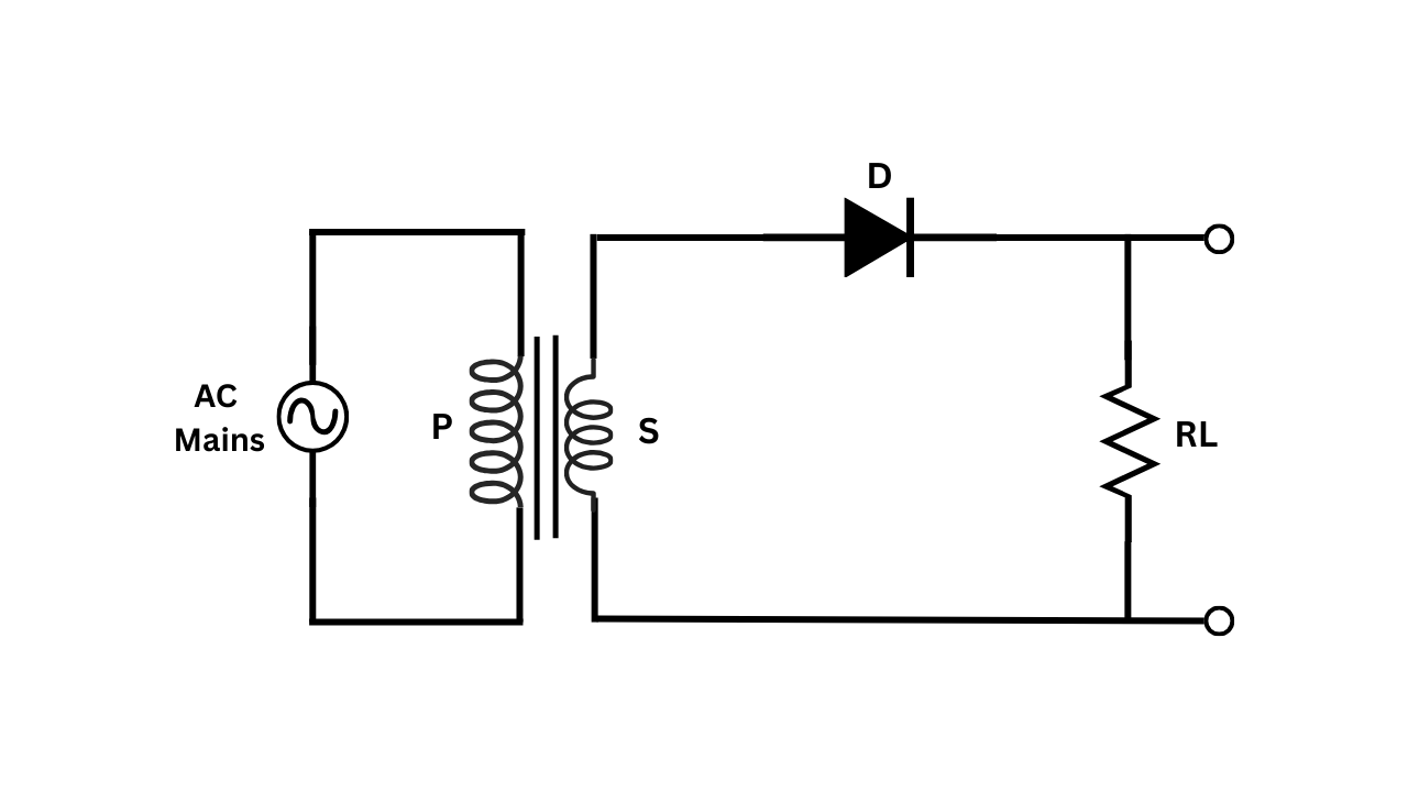
Figure 1: Circuit diagram of a Half Wave Rectifier without filter
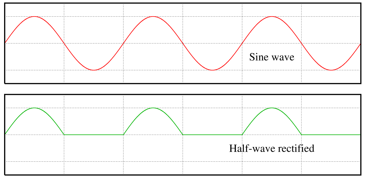
Figure 2: Input and Output Waveforms of Half Wave Rectifier
4. THEORY
A half-wave rectifier is a circuit that converts alternating current (AC) to direct current (DC) by eliminating one-half of the AC waveform. It consists of a single diode that conducts current only during the positive half-cycle of the input AC voltage.
Working Principle of Half Wave Rectifier:
The half-wave rectifier utilizes the unidirectional property of a diode to convert AC to pulsating DC. During operation, the circuit behaves in two ways:
1. Positive Half-Cycle: When the input AC voltage is positive (with respect to the reference terminal), the diode becomes forward biased. In this state, the diode conducts current and acts as a closed switch with a small voltage drop (typically 0.7V for silicon diodes). The load resistor receives the positive half of the input waveform minus this small diode voltage drop.
2. Negative Half-Cycle: When the input AC voltage is negative, the diode becomes reverse biased. In this state, the diode does not conduct (acts as an open switch), and no current flows through the circuit. Thus, the output voltage across the load resistor becomes zero during the negative half-cycle.
The resulting output is a pulsating DC voltage that varies from zero to a maximum value during each complete cycle of the input AC voltage. This output is not pure DC but contains significant AC components (ripple).
Characteristics of Half-Wave Rectifier:
- The output frequency is equal to the input frequency
- The rectifier utilizes only half of the input waveform
- The efficiency is lower compared to full-wave rectifiers
- The output contains significant ripple content
- The DC output voltage is less than half of the peak input voltage
In an ideal half-wave rectifier, if the input is a sinusoidal voltage $V_i = V_m \sin(\omega t)$, where $V_m$ is the peak value, the output voltage $V_o$ would be:
$V_o = V_m \sin(\omega t)$ for $0 \leq \omega t \leq \pi$ (positive half-cycle)
$V_o = 0$ for $\pi \leq \omega t \leq 2\pi$ (negative half-cycle)
However, in a practical half-wave rectifier using a silicon diode, the output voltage during the positive half-cycle is reduced by the diode forward voltage drop ($V_F \approx 0.7V$):
$V_o = V_m \sin(\omega t) - V_F$ for $0 \leq \omega t \leq \pi$ and $V_m \sin(\omega t) > V_F$
5. FORMULA
1. Average (DC) Output Voltage:
$V_{DC} = \frac{V_m}{\pi} = 0.318 \times V_m$
Where $V_m$ is the peak value of the input sinusoidal voltage
2. RMS Output Voltage:
$V_{RMS} = \frac{V_m}{2} = 0.5 \times V_m$
3. Ripple Factor:
$r = \frac{\sqrt{V_{RMS}^2 - V_{DC}^2}}{V_{DC}} = 1.21$
4. Form Factor:
$\text{Form Factor} = \frac{V_{RMS}}{V_{DC}} = \frac{V_m/2}{V_m/\pi} = \frac{\pi}{2} = 1.57$
5. Efficiency:
$\eta = \frac{\text{DC Power Output}}{\text{AC Power Input}} \times 100\% = 40.6\%$
6. Peak Inverse Voltage (PIV):
$\text{PIV} = V_m$
This is the maximum reverse voltage the diode must withstand
7. Transformer Utilization Factor (TUF):
$\text{TUF} = \frac{P_{DC}}{P_{trans}} = 0.287$
6. PROCEDURE
- Connect the circuit of half wave rectifier as shown in the circuit diagram:
- Connect the step-down transformer to reduce the AC mains voltage to a safer level (e.g., 12V AC).
- Connect one end of the transformer secondary to one end of the diode.
- Connect the other end of the diode to one end of the load resistor.
- Connect the other end of the load resistor to the other end of the transformer secondary.
- Switch on the power supply to the primary of the transformer.
- Using the CRO, observe and note the input waveform across the secondary of the transformer. Adjust the CRO controls to get a stable display.
- Observe and note the output waveform across the load resistor. Adjust the CRO controls if necessary.
- Measure the peak voltage of the input AC waveform ($V_m$) using the CRO.
- Measure the peak voltage of the output waveform across the load resistor using the CRO.
- Using a digital multimeter, measure the RMS voltage of the input AC waveform.
- Using a digital multimeter (in DC mode), measure the average (DC) voltage across the load resistor.
- Vary the input AC voltage and note down the corresponding values for different readings.
- Calculate the theoretical values for DC output voltage, RMS output voltage, ripple factor, form factor, and efficiency using the measured peak input voltage.
- Compare the half wave rectifier experimental values with the calculated theoretical values.
- Switch off the power supply and disassemble the circuit of half wave rectifier .
7. OBSERVATION TABLE
| S.No. | Input AC Voltage | Output DC Voltage | Ripple Factor (Calculated) |
|||
|---|---|---|---|---|---|---|
| RMS Value (Measured) $V_{in(RMS)}$ (V) |
Peak Value (Measured) $V_m$ (V) |
Peak Value (Measured) $V_{o(peak)}$ (V) |
DC Value (Measured) $V_{DC}$ (V) |
Theoretical DC Value $V_{DC(theo)} = \frac{V_m}{\pi}$ (V) |
||
| 1 | ||||||
| 2 | ||||||
| 3 | ||||||
| 4 | ||||||
| 5 | ||||||
8. CALCULATIONS
For a sample reading (e.g., Reading No. 1), perform the following calculations using the measured values:
1. Theoretical DC Output Voltage:
$V_{DC(theo)} = \frac{V_m}{\pi} = 0.318 \times V_m$
Where $V_m$ is the measured peak input voltage
2. Percentage Error in DC Output Voltage:
$\text{Error}(\%) = \frac{|V_{DC(theo)} - V_{DC(measured)}|}{V_{DC(theo)}} \times 100\%$
3. RMS Output Voltage:
$V_{RMS(theo)} = \frac{V_m}{2} = 0.5 \times V_m$
4. Ripple Factor of Half Wave Rectifier:
$r = \sqrt{\left(\frac{V_{RMS(theo)}}{V_{DC(theo)}}\right)^2 - 1} = \sqrt{\left(\frac{V_m/2}{V_m/\pi}\right)^2 - 1} = \sqrt{\left(\frac{\pi}{2}\right)^2 - 1} = 1.21$
5. Diode Forward Voltage Drop:
$V_F = V_m - V_{o(peak)}$
Where $V_{o(peak)}$ is the measured peak output voltage
Sample Calculation: (To be completed after taking actual readings)
Given:
- Peak input voltage ($V_m$) = ___ V
- Measured DC output voltage = ___ V
- Peak output voltage = ___ V
Theoretical DC output voltage, $V_{DC(theo)} = 0.318 \times V_m = 0.318 \times ___ = ___ V$
Percentage error = $\frac{|___ - ___|}{___} \times 100\% = ___ \%$
Ripple factor = 1.21 (theoretical value)
Diode forward voltage drop, $V_F = ___ - ___ = ___ V$
9. RESULT
1. A half-wave rectifier circuit without filter was constructed and studied successfully.
2. The input and output waveforms were observed on the CRO. The output waveform was found to be a pulsating DC with only the positive half-cycles of the input waveform present.
3. The average DC output voltage was measured to be approximately _____ V, which is close to the theoretical value of _____ V (calculated as $V_m/\pi$).
4. The percentage error between theoretical and measured DC output voltage was found to be approximately _____ %.
5. The diode forward voltage drop was observed to be approximately _____ V, which is typical for silicon diodes.
6. The ripple factor was calculated to be 1.21, which indicates significant ripple content in the output, confirming the need for a filter circuit in practical applications.
7. The experimental results verify the theoretical operation and characteristics of a half-wave rectifier circuit.
10. PRECAUTIONS
- Ensure all connections are tight and correct before switching on the power supply.
- Use appropriate ratings of components (diode, resistor) to prevent damage due to excessive current or voltage.
- Do not touch any part of the circuit when the power supply is on to avoid electric shock.
- Verify that the diode is connected in the correct direction (anode to the AC source and cathode to the load).
- Use the CRO probes with proper ground connections to avoid measurement errors.
- Set the CRO to appropriate voltage and time scales to get clear waveforms.
- Take multiple readings to minimize random errors in measurements.
- Ensure the voltage rating of the diode is at least twice the peak input voltage to prevent breakdown during the reverse-biased condition.
- Do not exceed the power rating of the load resistor to prevent it from burning.
- Switch off the power supply before making any changes to the circuit.
- Allow cooling time for components if the experiment is run for an extended period.
11. VIVA VOICE QUESTIONS
Q1. What is a rectifier and what are its types?
A rectifier is an electrical device that converts alternating current (AC) to direct current (DC). The main types of rectifiers are:
- Half-wave rectifier
- Full-wave rectifier (Center-tapped and Bridge)
- Controlled rectifiers (using SCRs, TRIACs, etc.)
Q2. What is the ripple factor of a half-wave rectifier? How does it compare to a full-wave rectifier?
The ripple factor of a half-wave rectifier is 1.21, which is higher compared to a full-wave rectifier (0.48). This indicates that a half-wave rectifier produces more ripple in the output and therefore provides lower quality DC compared to a full-wave rectifier.
Q3. Why is the efficiency of a half-wave rectifier limited to 40.6%?
The efficiency of a half-wave rectifier is limited to 40.6% because it utilizes only half of the input AC waveform (the positive half-cycle) while blocking the negative half-cycle. This means that nearly half of the available input power is not utilized, leading to poor efficiency.
Q4. What is the peak inverse voltage (PIV) rating of a diode in a half-wave rectifier?
In a half-wave rectifier, the PIV rating of the diode should be at least equal to the peak value of the input AC voltage ($V_m$). During the negative half-cycle, the diode is reverse-biased and must withstand this maximum reverse voltage.
Q5. What is the difference between half-wave and full-wave rectification?
Half-wave rectification converts only one half-cycle (positive or negative) of the AC input to DC, while full-wave rectification converts both positive and negative half-cycles to DC. Full-wave rectifiers provide higher DC output, lower ripple, better efficiency, and higher output frequency compared to half-wave rectifiers.
Q6. What is the output frequency of a half-wave rectifier if the input frequency is 50 Hz?
The output frequency of a half-wave rectifier is the same as the input frequency, which would be 50 Hz for a 50 Hz input. This is because the output consists of pulses occurring at the same rate as the input frequency.
Q7. Why do we need a filter circuit with a rectifier?
A filter circuit is needed with a rectifier to smooth out the pulsating DC output and reduce the ripple content. This helps in obtaining a steady DC voltage that is more suitable for powering electronic devices, which typically require a stable DC supply.
Q8. What is the form factor of a half-wave rectifier?
The form factor of a half-wave rectifier is $\pi/2$ (approximately 1.57). Form factor is defined as the ratio of RMS value to the average value of the output waveform.
Q9. How does the forward voltage drop of the diode affect the output of a half-wave rectifier?
The forward voltage drop of the diode (typically 0.7V for silicon diodes) reduces the output voltage of the rectifier. The actual output voltage during the conducting half-cycle will be the input voltage minus this diode drop. This effect is more significant at lower input voltages and less significant at higher input voltages.
Q10. What are the applications of half-wave rectifiers?
Despite their limitations, half-wave rectifiers are used in:
- Signal detection in radio receivers
- Simple power supplies where efficiency is not critical
- Battery charging circuits
- Signal demodulation
- Voltage multiplier circuits