
To Study the Variation of Magnetic Field Due to Helmholtz Coil and Single Coil Carrying Current
1. Aim
To study and verify the theoretical variation of the magnetic field along the axis of a single coil and a pair of Helmholtz Coil carrying current, and to determine the relationship between the magnetic field strength and position.
2. Apparatus Used
- Helmholtz coil setup (two identical circular coils of same radius mounted coaxially)
- Single circular coil
- Hall effect magnetic field sensor/Gaussmeter
- DC power supply (0-3A, 0-30V)
- Ammeter (0-3A)
- Connecting wires
- Travelling microscope/position measurement setup
- Rheostat/variable resistance
- Measuring scale/ruler
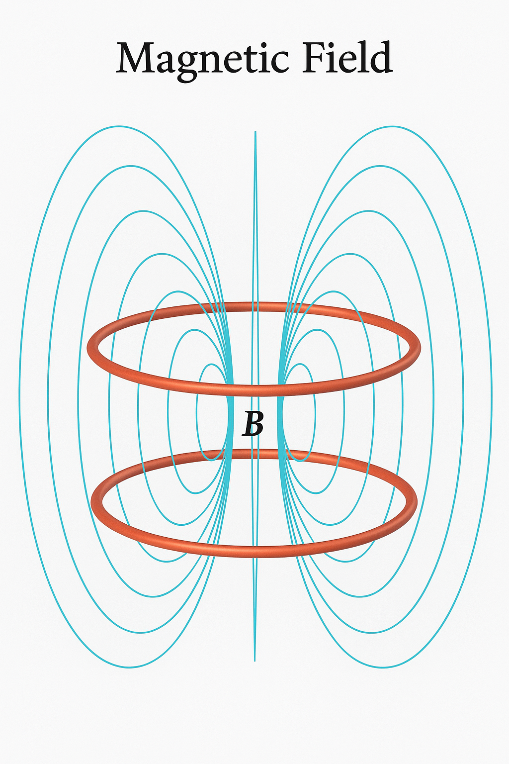
3. Diagram
4. Theory
The magnetic field due to a current-carrying circular coil is a fundamental concept in electromagnetism. When electric current flows through a conductor, it produces a magnetic field around it. For a circular coil, this field can be calculated using the Biot-Savart law.
Single Circular Coil:
Consider a circular coil of radius \(R\) carrying a current \(I\). The magnetic field \(B\) at a point on the axis of the coil at a distance \(x\) from the center of the coil is given by:
Where:
- \(\mu_0\) = Permeability of free space = \(4\pi \times 10^{-7}\) H/m
- \(I\) = Current flowing through the coil in amperes
- \(R\) = Radius of the coil in meters
- \(x\) = Distance along the axis from the center of the coil in meters
The field strength is maximum at the center of the coil (x = 0) and decreases as we move away from the center along the axis.
Helmholtz Coils:
A Helmholtz coil consists of two identical circular coils placed coaxially at a distance equal to the radius of either coil. If the same current flows through both coils in the same direction, the magnetic field in the central region between the coils is nearly uniform.
For Helmholtz coils, with each coil having radius \(R\) and carrying current \(I\), separated by a distance \(R\), the magnetic field at any point along the axis at a distance \(x\) from the center of the setup is the sum of the fields due to both coils:
At the center of the Helmholtz coil setup (x = 0), the magnetic field becomes:
The key feature of Helmholtz coils is that the magnetic field is highly uniform in the central region between the coils. This makes them useful for calibration and experiments requiring a uniform magnetic field.
5. Formula
The key formulas for this experiment are:
For Single Coil:
For Helmholtz Coils:
The theoretical value at the center of Helmholtz coils (x = 0):
Percentage error calculation:
6. Procedure
Part A: Single Coil
- Set up the single circular coil on the stand and ensure it's properly aligned.
- Connect the coil to the DC power supply through an ammeter and rheostat.
- Position the Hall effect sensor/Gaussmeter at the center of the coil (x = 0).
- Switch on the power supply and adjust the current to a suitable value (e.g., 1A) using the rheostat.
- Record the magnetic field reading from the Gaussmeter.
- Move the sensor along the axis of the coil at regular intervals (e.g., 1 cm steps) away from the center.
- Record the magnetic field strength at each position.
- Continue taking readings until the field becomes negligibly small.
- Repeat the measurements for at least two different current values.
Part B: Helmholtz Coils
- Set up the Helmholtz coils with a separation equal to the radius of either coil.
- Connect both coils in series to ensure the same current flows through them.
- Connect the coils to the DC power supply through an ammeter and rheostat.
- Position the Hall effect sensor/Gaussmeter at the center of the Helmholtz coil setup (midway between the two coils).
- Switch on the power supply and adjust the current to a suitable value (e.g., 1A).
- Record the magnetic field reading from the Gaussmeter.
- Move the sensor along the axis of the coils at regular intervals (e.g., 1 cm steps) away from the center.
- Record the magnetic field strength at each position.
- Continue taking readings until you've covered the entire region between the coils and some distance beyond.
- Repeat the measurements for at least two different current values.
7. Observation Table
Part A: Single Coil
Radius of the coil (R) = ________ cm
Current in the coil (I) = ________ A
| S.No. | Position (x) [cm] | Magnetic Field (B) [mT] | Theoretical B [mT] | Percentage Error [%] |
|---|---|---|---|---|
| 1 | ||||
| 2 | ||||
| 3 | ||||
| 4 | ||||
| 5 | ||||
| 6 | ||||
| 7 | ||||
| 8 |
Part B: Helmholtz Coils
Radius of each coil (R) = ________ cm
Separation between coils = ________ cm
Current in the coils (I) = ________ A
| S.No. | Position (x) [cm] | Magnetic Field (B) [mT] | Theoretical B [mT] | Percentage Error [%] |
|---|---|---|---|---|
| 1 | ||||
| 2 | ||||
| 3 | ||||
| 4 | ||||
| 5 | ||||
| 6 | ||||
| 7 | ||||
| 8 |
8. Calculations
For Single Coil:
The theoretical magnetic field at a distance x from the center of a single coil is calculated using:
For example, at position x = 0 (center of the coil):
Substituting \(\mu_0 = 4\pi \times 10^{-7}\) H/m, I = [measured current], R = [measured radius]:
Btheoretical = ________ mT
For Helmholtz Coils:
The theoretical magnetic field at a position x along the axis of Helmholtz coils is calculated using:
For example, at position x = 0 (center between the coils):
Substituting \(\mu_0 = 4\pi \times 10^{-7}\) H/m, I = [measured current], R = [measured radius]:
Btheoretical = ________ mT
Percentage Error:
For example, if Btheoretical = 0.50 mT and Bexperimental = 0.48 mT:
Percentage Error = |(0.50 - 0.48)|/0.50 × 100% = 4.0%
9. Result
From the experiment, we can conclude the following:
- The magnetic field along the axis of a single coil varies with distance according to the relation \(B = \frac{\mu_0 I R^2}{2(R^2 + x^2)^{3/2}}\). The field is maximum at the center and decreases as we move away from the center along the axis.
- For the Helmholtz coils, the magnetic field is nearly uniform in the central region between the coils. This confirms the property of Helmholtz coils to produce a uniform magnetic field in a defined region.
- The experimental values of the magnetic field strengths at various positions show good agreement with the theoretical values, with an average percentage error of _______.
- The magnetic field strength is directly proportional to the current flowing through the coils, as predicted by theory.
10. Precautions
- Ensure that there are no ferromagnetic objects near the experimental setup as they can distort the magnetic field readings.
- The Hall effect sensor/Gaussmeter should be calibrated properly before use.
- The current should be kept constant throughout the measurements for a particular set of readings.
- The Hall probe should be aligned properly along the axis of the coil(s) to measure the axial component of the magnetic field accurately.
- Avoid overheating of the coils by not passing excessive current through them for extended periods.
- Ensure that the coils are properly aligned coaxially, especially for the Helmholtz coil setup.
- For Helmholtz coils, verify that the separation between the coils is exactly equal to the radius of either coil.
- Take multiple readings at each position and use the average value to minimize random errors.
- Ensure that the connections are tight and secure to avoid fluctuations in current.
- Keep electronic devices away from the experimental setup to avoid interference.
11. Viva Voice Questions
-
What is a Helmholtz coil and what is its special property?
A Helmholtz coil consists of two identical circular coils placed coaxially at a distance equal to the radius of either coil. Its special property is that it produces a highly uniform magnetic field in the central region between the coils when the same current flows through both coils in the same direction.
-
Why is the magnetic field more uniform in Helmholtz coils compared to a single coil?
In Helmholtz coils, the field gradients from each coil compensate for each other in the central region. Mathematically, the first and second derivatives of the magnetic field with respect to position vanish at the center, resulting in a more uniform field over a larger region compared to a single coil.
-
What happens to the magnetic field if the separation between the coils is not equal to the radius?
If the separation between the coils is not equal to the radius, the uniformity of the magnetic field in the central region will be compromised. The optimal uniformity occurs precisely when the separation equals the radius.
-
How does the magnetic field at the center of a single coil depend on its radius?
The magnetic field at the center of a single coil is inversely proportional to its radius. As per the formula \(B = \frac{\mu_0 I}{2R}\), if the radius increases, the magnetic field decreases, and vice versa.
-
What is the significance of Biot-Savart law in this experiment?
The Biot-Savart law is fundamental to calculating the magnetic field due to a current-carrying conductor. In this experiment, we use the integrated form of this law to derive the expressions for the magnetic field along the axis of circular coils.
-
Why do we use a Hall effect sensor/Gaussmeter instead of a compass needle to measure the magnetic field?
A Hall effect sensor provides direct, quantitative measurements of the magnetic field strength, while a compass needle only shows direction. The sensor is also more sensitive and can detect smaller variations in the field strength, making it suitable for precise measurements required in this experiment.
-
What are some practical applications of Helmholtz coils?
Helmholtz coils are used in various applications requiring a uniform magnetic field, such as: calibrating magnetic field sensors, cancelling Earth's magnetic field in experiments, MRI calibration, particle beam control in accelerators, and in biomedical research for controlled magnetic field exposure studies.
-
How would the magnetic field change if we reverse the direction of current in one of the coils in the Helmholtz setup?
If the current direction is reversed in one of the coils, the magnetic fields from the two coils would oppose each other instead of adding up. This would create a magnetic field gradient or a "magnetic field zero" in the central region, rather than a uniform field.
-
What is the effect of increasing the number of turns in the coil on the magnetic field strength?
The magnetic field strength is directly proportional to the number of turns in the coil. Doubling the number of turns would double the magnetic field strength for the same current, as the effective current becomes N times the actual current, where N is the number of turns.
-
How does the Earth's magnetic field affect your measurements, and how would you account for it?
The Earth's magnetic field (approximately 25-65 μT depending on location) can add to or subtract from your measurements depending on the orientation of your experimental setup. To account for it, you should either shield the setup from external fields, or take readings with zero current and subtract them from your measurements to get the true field due to the coils alone.