
Verification of Malus's Law
Laboratry Manual
1 Aim
2 Apparatus Used
- Light source (LED or Laser)
- Polarizer (Fixed)
- Analyzer (Rotatable)
- Photodetector or Light sensor
- Digital multimeter
- Rotating mount with angular scale
- Optical bench
- Connecting wires
3 Diagram
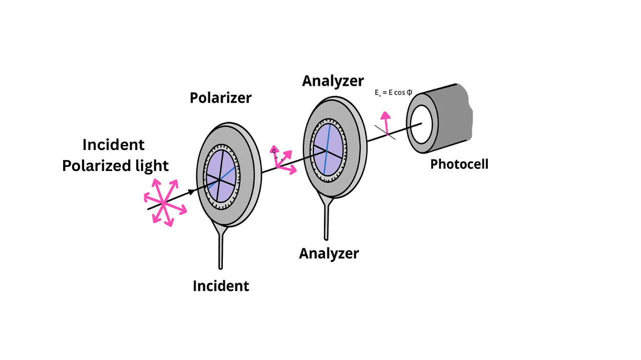
4 Theory
When unpolarized light passes through a polarizer, it becomes linearly polarized. If this polarized light then passes through a second polarizer (called an analyzer), the intensity of the transmitted light depends on the angle θ between the transmission axes of the polarizer and analyzer.
According to Malus's Law, discovered by Étienne-Louis Malus in 1808, the intensity of light transmitted through the analyzer is given by:
Where:
- I = Intensity of transmitted light
- I₀ = Intensity of incident polarized light
- θ = Angle between polarizer and analyzer axes
This law demonstrates that:
- Maximum transmission occurs when θ = 0° (parallel axes)
- Minimum transmission (zero) occurs when θ = 90° (crossed axes)
- The relationship follows a cosine-squared dependence
5 Formula
$I = I_0 \cos^2\theta$
$\frac{I}{I_0} = \cos^2\theta$
$\sqrt{\frac{I}{I_0}} = |\cos\theta|$
6 Procedure
7 Observation Table
| Sr. No. | Angle θ (degrees) | cos θ | cos² θ | Observed Intensity I (mV) | I/I₀ | % Error |
|---|---|---|---|---|---|---|
| 1 | 0° | 1.000 | 1.000 | |||
| 2 | 10° | 0.985 | 0.970 | |||
| 3 | 20° | 0.940 | 0.883 | |||
| 4 | 30° | 0.866 | 0.750 | |||
| 5 | 40° | 0.766 | 0.587 | |||
| 6 | 50° | 0.643 | 0.413 | |||
| 7 | 60° | 0.500 | 0.250 | |||
| 8 | 70° | 0.342 | 0.117 | |||
| 9 | 80° | 0.174 | 0.030 | |||
| 10 | 90° | 0.000 | 0.000 |
Note: I₀ = Maximum intensity at θ = 0° = _____ mV
8 Calculations
$\text{Error \%} = \frac{|\text{Theoretical} - \text{Observed}|}{\text{Theoretical}} \times 100\%$
Sample Calculation:
For θ = 30°:
- Theoretical value: cos²(30°) = (0.866)² = 0.750
- If observed I = 375 mV and I₀ = 500 mV
- Then I/I₀ = 375/500 = 0.750
- Error % = |0.750 - 0.750|/0.750 × 100% = 0%
9 Result
The experimental results verify Malus's Law within acceptable experimental error limits. The intensity of transmitted polarized light follows the relationship:
Key Observations:
- Maximum transmission occurs at θ = 0° (parallel polarizers)
- Minimum transmission occurs at θ = 90° (crossed polarizers)
- The intensity variation follows the predicted cosine-squared relationship
- Average percentage error: _____%
Conclusion: Malus's Law is successfully verified experimentally.
10 Precautions
- Ensure proper alignment of all optical components on the bench.
- Allow the light source to stabilize before taking readings.
- Handle polarizers carefully to avoid scratches or fingerprints.
- Take multiple readings and calculate average values for better accuracy.
- Ensure the photodetector is properly calibrated and connected.
- Avoid stray light by conducting the experiment in a darkened room.
- Rotate the analyzer slowly and steadily for consistent readings.
- Check for zero error in the measuring instruments before starting.
- Maintain constant distance between components throughout the experiment.
- Record the angular positions carefully using the graduated scale.
11 Viva Voice Questions
A: Malus's Law states that the intensity of polarized light transmitted through an analyzer varies as the square of the cosine of the angle between the transmission axes. It was discovered by Étienne-Louis Malus in 1808.
A: At θ = 0°, maximum light is transmitted (I = I₀). At θ = 90°, no light is transmitted (I = 0) as the polarizers are crossed.
A: A polarizer converts unpolarized light into polarized light. An analyzer is used to analyze the polarization state of already polarized light.
A: Sunglasses, LCD displays, photography filters, stress analysis, optical instruments, and 3D cinema technology.
A: The photodetector converts light intensity into electrical signals (voltage/current) which can be measured and is proportional to the incident light intensity.
A: I = I₀ cos²θ, where I is transmitted intensity, I₀ is incident intensity, and θ is the angle between polarizer axes.
A: Misalignment of components, stray light, instrumental errors, non-ideal polarizers, and environmental factors.