
Study of OP AMP as an Inverting Amplifier
1. Aim
To design, assemble, and study the Operational Amplifier (OP AMP) circuit as an inverting amplifier, verify its output characteristics, and determine its voltage gain experimentally.
2. Apparatus Used
- IC 741 Operational Amplifier
- Resistors (1kΩ, 10kΩ, and various values as required)
- Breadboard
- DC Power Supply (±15V)
- Digital Multimeter or CRO (Cathode Ray Oscilloscope)
- Function Generator
- Connecting wires
- Digital Oscilloscope (optional)
3. Circuit Diagram
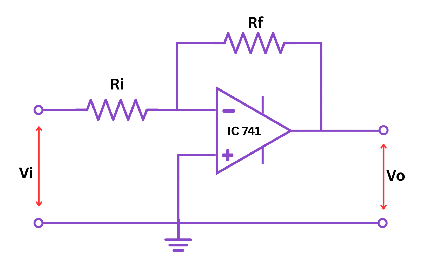
Figure: Op-Amp as an Inverting Amplifer
4. Theory
An operational amplifier (OP AMP) is a high-gain electronic voltage amplifier with differential inputs and, usually, a single-ended output. In an inverting amplifier configuration, the output signal is inverted (180° phase shift) with respect to the input signal.
The inverting amplifier is one of the most useful and versatile op-amp configurations. In this configuration:
- The input signal is applied to the inverting terminal (negative) through a resistor Ri
- The non-inverting terminal (positive) is connected to ground
- A feedback resistor Rf is connected between the output and the inverting input
When operating within its linear region, an ideal op-amp has the following characteristics:
- Infinite open-loop gain
- Infinite input impedance (no current flows into the input terminals)
- Zero output impedance
In practice, real op-amps have very high (but finite) open-loop gain, very high input impedance, and very low output impedance. These properties allow us to make the following assumptions for analysis:
The voltage difference between the inverting and non-inverting inputs is approximately zero. This creates a "virtual ground" at the inverting input when the non-inverting input is grounded. This concept is key to understanding the operation of the inverting amplifier.
Due to the virtual ground principle and the high input impedance, we can say that:
Where $I_{in}$ is the current through the input resistor and $I_f$ is the current through the feedback resistor.
5. Formula
The voltage gain of an inverting amplifier can be determined by:
Where:
- $A_v$ = Voltage gain
- $V_{out}$ = Output voltage
- $V_{in}$ = Input voltage
- $R_f$ = Feedback resistor
- $R_i$ = Input resistor
The negative sign indicates that the output is 180° out of phase with the input (inverted).
For deriving this formula:
Where $V_-$ is the voltage at the inverting input. Since this is a virtual ground, $V_- \approx 0$.
Similarly, the current through the feedback resistor is:
Since $I_{in} = I_f$ (by Kirchhoff's Current Law at the inverting input node):
Rearranging:
6. Procedure
- Connect the circuit on the breadboard as per the circuit diagram.
- Power the OP AMP with ±15V DC supply.
- Apply a sinusoidal input signal (approximately 0.5V peak-to-peak at 1 kHz) to the input resistor Ri.
- Initially, set Rf = 10kΩ and Ri = 1kΩ for a gain of -10.
- Observe the output waveform on the CRO or oscilloscope.
- Measure the peak-to-peak amplitude of both input and output signals.
- Calculate the practical gain as the ratio of output to input voltage (Vout/Vin).
- Repeat steps 3-7 for different values of Rf (keeping Ri constant) to obtain different gains.
- Alternatively, repeat steps 3-7 for different input signal frequencies to study the frequency response of the amplifier.
- Record all observations in the observation table.
- Compare the theoretical gain (-Rf/Ri) with the experimental gain for each configuration.
7. Observation Table
| S.No. | Input Resistor (Ri) in kΩ | Feedback Resistor (Rf) in kΩ | Theoretical Gain (-Rf/Ri) | Input Voltage (Vin) in V | Output Voltage (Vout) in V | Practical Gain (Vout/Vin) | Error (%) |
|---|---|---|---|---|---|---|---|
| 1 | |||||||
| 2 | |||||||
| 3 | |||||||
| 4 | |||||||
| 5 |
Additional observations for frequency response (optional):
| S.No. | Frequency (Hz) | Input Voltage (Vin) in V | Output Voltage (Vout) in V | Gain (Vout/Vin) |
|---|---|---|---|---|
| 1 | ||||
| 2 | ||||
| 3 |
8. Calculations
For each set of readings, calculate:
1. Theoretical Gain:
2. Practical Gain:
3. Percentage Error:
Sample Calculation:
Let's say for a configuration with Ri = 1kΩ and Rf = 10kΩ:
- Theoretical Gain = -(10kΩ/1kΩ) = -10
- Measured Vin = 0.5V and Vout = -4.8V
- Practical Gain = -4.8V/0.5V = -9.6
- Error (%) = |(-10-(-9.6))/(-10)| × 100 = |0.4/10| × 100 = 4%
9. Result
From this experiment, we have:
- Successfully designed and assembled an inverting amplifier circuit using OP AMP 741.
- Verified that the output is 180° out of phase with the input (inverted).
- Confirmed that the voltage gain is approximately equal to the ratio -Rf/Ri.
- The average percentage error between theoretical and practical gain was found to be _____% (to be filled after the experiment).
- Observed that the voltage gain remains fairly constant across the measured frequency range (if frequency response was studied).
10. Precautions
- Ensure proper power supply connections to the OP AMP (±15V).
- Check for proper grounding of the circuit.
- Make sure the input signal amplitude is within the linear operating range of the amplifier to avoid clipping.
- Avoid loose connections on the breadboard.
- Handle the IC chip carefully to avoid static discharge damage.
- Keep the input frequency within the bandwidth of the OP AMP for accurate measurements.
- Verify the pin configuration of the IC 741 before connections.
- Use appropriate scale settings on the oscilloscope for clear waveform observation.
- For high gain configurations, be aware of potential oscillations and use appropriate decoupling capacitors if necessary.
- Ensure that the OP AMP is not operating in saturation mode.
11. Viva Voce Questions
Q1. What is an operational amplifier?
An operational amplifier (OP AMP) is a high-gain electronic voltage amplifier with a differential input and, usually, a single-ended output. It is designed to be used with external feedback components such as resistors and capacitors between its output and input terminals.
Q2. Why is this configuration called an "inverting" amplifier?
It is called an inverting amplifier because the output voltage is 180° out of phase with the input voltage, meaning the output has the opposite polarity to the input signal (indicated by the negative sign in the gain formula).
Q3. What is meant by virtual ground in the inverting amplifier?
Virtual ground refers to the condition at the inverting input terminal where the voltage is approximately zero (ground potential) but no current flows into the ground. It occurs due to the high open-loop gain of the op-amp and the negative feedback arrangement.
Q4. How does the input impedance of an inverting amplifier compare to that of a non-inverting amplifier?
The input impedance of an inverting amplifier is equal to the value of the input resistor Ri, which is typically lower than the input impedance of a non-inverting amplifier, which is very high (ideally infinite).
Q5. What happens if we remove the feedback resistor Rf from the circuit?
If we remove the feedback resistor, the op-amp will operate in open-loop configuration with extremely high gain. This would typically cause the output to saturate at either the positive or negative supply voltage, depending on the input signal polarity.
Q6. What are the applications of an inverting amplifier?
Inverting amplifiers are used in various applications including signal conditioning, active filters, summing amplifiers, audio amplifiers, differential amplifiers, and in analog computers for performing mathematical operations.
Q7. What is meant by saturation in an OP AMP?
Saturation in an OP AMP occurs when the output voltage reaches its maximum limit, which is slightly less than the supply voltage. In this state, the op-amp cannot produce any higher output voltage regardless of input changes, leading to clipping of the output signal.
Q8. Why is there usually some discrepancy between theoretical and practical gain values?
Discrepancies can arise due to several factors including: non-ideal characteristics of real op-amps (finite open-loop gain, non-zero input bias currents), resistor tolerance values, temperature effects, presence of noise, and measurement errors.
Q9. What would happen if Rf is less than Ri in an inverting amplifier?
If Rf is less than Ri, the gain magnitude will be less than 1 (|Av| < 1), resulting in attenuation of the input signal while still inverting it.
Q10. How would you modify this circuit to create a summing amplifier?
To create a summing amplifier, additional input resistors could be connected to the inverting input terminal. Each input would contribute to the output according to the ratio of the feedback resistor to the respective input resistor, allowing the circuit to add multiple weighted input signals.