
TO STUDY CHARACTERISTICS OF SILICON CONTROLLED RECTIFIER (SCR)
1. AIM
To study and plot the V-I characteristics of Silicon Controlled Rectifier (SCR) and determine its important parameters:
- Forward breakover voltage
- Holding current
- Latching current
- Forward and reverse blocking characteristics
2. APPARATUS USED
- Silicon Controlled Rectifier (SCR) (BT151 or equivalent)
- DC Power Supply (0-30V)
- Variable DC Power Supply for gate (0-5V)
- Digital Multimeters (2 nos.)
- Rheostat (1kΩ, 2W)
- Gate Resistor (470Ω, 1/2W)
- Load Resistor (100Ω, 5W)
- Connecting wires
- Breadboard
3. DIAGRAM
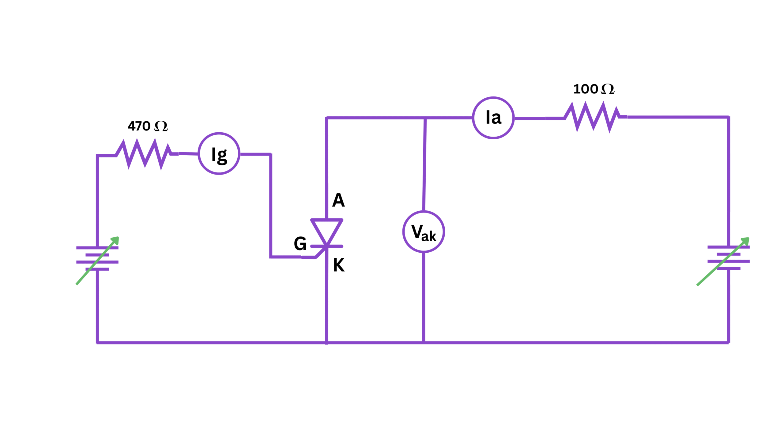
Fig 1: Circuit diagram for studying Silicon Controlled Rectifier characteristics
4. THEORY
A Silicon Controlled Rectifier (SCR) is a four-layer (PNPN) semiconductor device that acts as a controlled switch. It is a unidirectional device (conducts current only in one direction) with three terminals:
- Anode (A): Connected to the p-layer of the PNPN structure
- Cathode (K): Connected to the n-layer of the PNPN structure
- Gate (G): Connected to the inner p-layer and used as a control terminal
An Silicon Controlled Rectifier remains in the "OFF" state (high impedance) until it is triggered by applying a positive voltage to the gate terminal. Once triggered, it switches to the "ON" state (low impedance) and continues to conduct even if the gate signal is removed. This behavior is called "latching."
The Silicon Controlled Rectifier will remain in conduction until the current flowing through it falls below a minimum value called the "holding current." This is the principle of operation that makes SCRs useful in power control applications.
Key characteristics of an Silicon Controlled Rectifier include:
- Forward Blocking Mode: Anode is positive with respect to cathode, but no gate current is applied. SCR blocks current flow (high impedance).
- Forward Conduction Mode: SCR is triggered by gate current and conducts heavily from anode to cathode (low impedance).
- Reverse Blocking Mode: Anode is negative with respect to cathode. SCR blocks current flow (high impedance).
Important parameters of an Silicon Controlled Rectifier include:
- Forward Breakover Voltage (VBO): The voltage at which SCR starts conducting without gate trigger.
- Holding Current (IH): Minimum anode current required to maintain the SCR in conduction state.
- Latching Current (IL): Minimum anode current required to maintain conduction immediately after Silicon Controlled Rectifier is turned on and gate signal is removed.
- Gate Trigger Current (IGT): Minimum gate current required to trigger the Silicon Controlled Rectifier.
- Gate Trigger Voltage (VGT): Minimum gate voltage required to trigger the Silicon Controlled Rectifier.
5. FORMULA
The relationship between anode current (IA), gate current (IG), and anode-cathode voltage (VAK) can be represented using the following expressions:
\[ I_A = f(V_{AK}, I_G) \]
In forward blocking state:
\[ I_A \approx I_{CBO} \text{ for } V_{AK} < V_{BO} \text{ and } I_G = 0 \]
In forward conduction state:
\[ V_{AK} \approx 1\text{ to }2\text{ V} \text{ for } I_A > I_H \]
The forward breakover voltage (VBO) decreases with increasing gate current:
\[ V_{BO}(I_{G2}) < V_{BO}(I_{G1}) \text{ for } I_{G2} > I_{G1} \]
6. PROCEDURE
A. V-I Characteristics without Gate Current (IG = 0)
- Connect the circuit as shown in the diagram with the gate terminal open (no gate current).
- Set the DC power supply to minimum voltage.
- Gradually increase the anode voltage (VAK) and record the corresponding anode current (IA).
- Continue increasing the voltage until the SCR turns on (breakover point).
- Note the forward breakover voltage (VBO).
- After Silicon Controlled Rectifier turns on, gradually decrease the anode voltage and observe the anode current.
- Record the voltage and current values at which the SCR turns off (holding point).
- Note the holding current (IH).
B. V-I Characteristics with Different Gate Currents
- Connect the gate circuit with the gate resistor (RG).
- Set the gate supply voltage to provide a specific gate current (IG1).
- Starting from zero, gradually increase the anode voltage and record the corresponding anode current.
- Note the voltage at which Silicon Controlled Rectifier turns on at this gate current.
- After Silicon Controlled Rectifier turns on, record the minimum current required to keep it in conduction state.
- Repeat steps 2-5 for different gate currents (IG2, IG3, etc.).
C. Measuring Latching Current
- Set the anode voltage to a low value (around 5V).
- Apply a momentary gate pulse to turn on the Silicon Controlled Rectifier.
- Adjust the rheostat to find the minimum anode current at which the SCR remains on when the gate signal is removed.
- This is the latching current (IL).
D. Reverse Characteristics
- Connect the Silicon Controlled Rectifier in reverse configuration (anode connected to negative and cathode to positive terminal of supply).
- Gradually increase the voltage and observe the leakage current.
- Be careful not to exceed the reverse breakdown voltage of the Silicon Controlled Rectifier.
7. OBSERVATION TABLE
Table 1: V-I Characteristics without Gate Current (IG = 0)
| S. No. | Anode-Cathode Voltage VAK (V) | Anode Current IA (mA) | Remarks |
|---|---|---|---|
| 1 | Forward blocking | ||
| 2 | Forward blocking | ||
| 3 | Forward blocking | ||
| 4 | Breakover point | ||
| 5 | Forward conduction | ||
| 6 | Forward conduction | ||
| 7 | Holding point |
Table 2: V-I Characteristics with Gate Current IG1 = _____ mA
| S. No. | Anode-Cathode Voltage VAK (V) | Anode Current IA (mA) | Remarks |
|---|---|---|---|
| 1 | Forward blocking | ||
| 2 | Forward blocking | ||
| 3 | Turn-on point | ||
| 4 | Forward conduction | ||
| 5 | Forward conduction |
Table 3: V-I Characteristics with Gate Current IG2 = _____ mA
| S. No. | Anode-Cathode Voltage VAK (V) | Anode Current IA (mA) | Remarks |
|---|---|---|---|
| 1 | Forward blocking | ||
| 2 | Forward blocking | ||
| 3 | Turn-on point | ||
| 4 | Forward conduction | ||
| 5 | Forward conduction |
Table 4: Summary of Parameters
| Parameter | Value | Unit |
|---|---|---|
| Forward Breakover Voltage (VBO) at IG = 0 | V | |
| Holding Current (IH) | mA | |
| Latching Current (IL) | mA | |
| Turn-on Voltage at IG1 | V | |
| Turn-on Voltage at IG2 | V |
8. CALCULATIONS
From the recorded observations, the following calculations can be performed:
-
Forward Breakover Voltage (VBO):
This is directly read from Table 1, at the point where the SCR transitions from blocking to conduction state without gate current.
\[ V_{BO} = \text{(Value from Table 1, row 4)} \text{ V} \]
-
Holding Current (IH):
This is directly read from Table 1, at the point where the SCR turns off as current is reduced.
\[ I_H = \text{(Value from Table 1, row 7)} \text{ mA} \]
-
Gate Current Calculation:
Gate current can be calculated using Ohm's law:
\[ I_G = \frac{V_G - V_{GK}}{R_G} \]
Where:
VG = Gate supply voltage
VGK = Gate-Cathode voltage (typically 0.7V when conducting)
RG = Gate resistor value
-
Forward Voltage Drop in Conduction:
The forward voltage drop across SCR in conduction state can be calculated as the average from the observations in conduction mode:
\[ V_F = \frac{\sum V_{AK} \text{ (in conduction)}}{n} \]
Where n is the number of readings in conduction state.
9. RESULT
The V-I characteristics of the Silicon Controlled Rectifier (SCR) have been studied and the following parameters are determined:
- Forward breakover voltage (VBO) = _____ V
- Holding current (IH) = _____ mA
- Latching current (IL) = _____ mA
- Forward voltage drop in conduction state = _____ V
From the characteristics curve, it is observed that:
- The SCR acts as a high impedance device in its forward blocking region until the breakover voltage is reached or gate current is applied.
- Once triggered, the SCR remains in conduction state even after removing the gate signal until the anode current falls below the holding current.
- The forward breakover voltage decreases with increasing gate current.
- In the conduction state, the SCR exhibits a low forward voltage drop (typically 1-2V) regardless of the anode current magnitude.
10. PRECAUTIONS
- Always connect the circuit with power supply turned off.
- Never exceed the maximum rated values of voltage and current for the SCR.
- Ensure proper heat sink is used if higher currents are to be handled by the SCR.
- Use appropriate gate resistance to limit the gate current within the specified range.
- Verify all connections before turning on the power supply.
- Do not disconnect the circuit when the SCR is conducting as it may cause high voltage inductive kicks.
- Handle the SCR carefully as it is sensitive to static electricity.
- Be cautious while measuring the reverse characteristics to avoid breakdown.
- Ensure that all measuring instruments are properly calibrated.
- Do not touch any part of the circuit when power is on.