
Zener Regulated Power Supply
1. Aim
To study and analyze the behavior of a Zener regulated power supply circuit and verify the voltage regulation characteristics of a Zener diode.
2. Apparatus Used
- Step-down transformer (230V AC primary to 12V or 15V AC secondary)
- Bridge rectifier using IN4007 diodes (or 1N4007 diode bridge module)
- Filter capacitor (1000 μF, 25V)
- Load resistor (variable: 100Ω to 1kΩ)
- Series resistor (470Ω, 1W)
- Digital multimeter (2 units)
- Connecting wires
- Breadboard
- Regulated DC power supply (0-30V) as an alternative to transformer and rectifier
3. Circuit Diagram
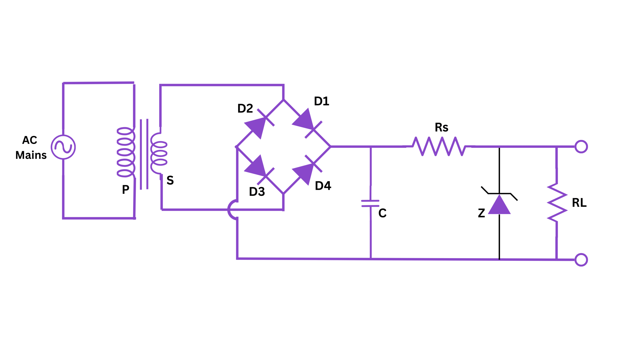
Fig 1. Zener Regulated Power Supply Circuit
4. Theory
A Zener diode is a special type of semiconductor diode that allows current to flow not only in the forward direction like a normal diode but also in the reverse direction when the voltage applied across its terminals exceeds the breakdown voltage (known as the Zener voltage).
When operated in the breakdown region, a Zener diode maintains a nearly constant voltage across its terminals over a wide range of current values. This property makes Zener diodes extremely useful as voltage regulators or voltage references in electronic circuits.
The key principle of a Zener regulated power supply is that:
- The input unregulated DC voltage must be higher than the Zener voltage.
- A series resistor (Rs) limits the current through the Zener diode.
- When the load draws less current, the Zener conducts more current, keeping the voltage constant.
- When the load draws more current, the Zener conducts less current, still maintaining constant voltage.
In the experiment of zener regulated power supply, we first convert AC voltage to unregulated DC using a bridge rectifier and capacitor filter. Then, we use a Zener diode to maintain a constant output voltage regardless of variations in input voltage or load current (within specified limits).
Zener Diode Operation: When connected in reverse bias with voltage greater than its breakdown voltage, a Zener diode operates in the breakdown region. In this region, it maintains an almost constant voltage (the Zener voltage) across it despite significant changes in the current flowing through it.
5. Formula
The following formulas are used in Zener regulated power supply calculations:
1. Current through series resistor (Rs):
$$I_s = \frac{V_{in} - V_z}{R_s}$$
2. Current through Zener diode:
$$I_z = I_s - I_L$$
3. Current through load:
$$I_L = \frac{V_z}{R_L}$$
4. Power dissipated in Zener diode:
$$P_z = V_z \times I_z$$
5. Line regulation:
$$\text{Line Regulation} = \frac{\Delta V_{out}}{\Delta V_{in}} \times 100\%$$
6. Load regulation:
$$\text{Load Regulation} = \frac{V_{NL} - V_{FL}}{V_{FL}} \times 100\%$$
Where:
- $V_{in}$ = Input voltage
- $V_z$ = Zener voltage
- $R_s$ = Series resistance
- $R_L$ = Load resistance
- $I_s$ = Series current
- $I_z$ = Zener current
- $I_L$ = Load current
- $P_z$ = Power dissipated in Zener diode
- $V_{NL}$ = No-load output voltage
- $V_{FL}$ = Full-load output voltage
6. Procedure
- Circuit Setup:
- Connect the circuit of zener regulated power supply as shown in the circuit diagram.
- The transformer steps down the 230V AC to 12V or 15V AC.
- The bridge rectifier converts AC to pulsating DC.
- The capacitor filters the pulsating DC to obtain smoother DC.
- Connect the series resistor Rs, Zener diode, and variable load resistor as shown.
- Alternatively: Instead of the transformer, rectifier, and filter, use a variable DC power supply as the input to the Zener circuit.
- Initial Measurements:
- Set the input voltage to a value higher than the Zener rating (e.g., for a 5.6V Zener, set input to about 12V).
- Keep the load resistance at maximum value (minimum load current).
- Measure and record the Zener voltage (output voltage).
- Line Regulation Test:
- Keep the load resistance constant.
- Vary the input voltage in steps (e.g., 8V, 10V, 12V, 14V, 16V).
- For each input voltage value, measure and record the output voltage.
- Calculate the line regulation.
- Load Regulation Test:
- Keep the input voltage constant at a suitable value above the Zener voltage.
- Vary the load resistance in steps and measure the corresponding load current.
- For each load resistance value, measure and record the output voltage.
- Calculate the load regulation.
- Zener Current Measurement:
- With the circuit still connected, measure the current through the series resistor.
- Calculate the Zener diode current using the formula: Iz = Is - IL.
- Efficiency Calculation:
- Calculate the power input to the circuit: Pin = Vin × Is
- Calculate the power output to the load: Pout = Vz × IL
- Calculate efficiency: η = (Pout/Pin) × 100%
- Shutdown: Turn off the power supply and disconnect the circuit.
7. Observation Tables
Table 1: Line Regulation Test
| S.No. | Input Voltage (Vin) V | Output Voltage (Vout) V | Change in Output (ΔVout) V | Change in Input (ΔVin) V | Line Regulation (%) |
|---|---|---|---|---|---|
| 1 | - | - | - | ||
| 2 | |||||
| 3 | |||||
| 4 | |||||
| 5 |
Table 2: Load Regulation Test
| S.No. | Load Resistance (RL) Ω | Load Current (IL) mA | Output Voltage (Vout) V | Zener Current (Iz) mA | Remarks |
|---|---|---|---|---|---|
| 1 | |||||
| 2 | |||||
| 3 | |||||
| 4 | |||||
| 5 |
Table 3: Power and Efficiency Calculation
| S.No. | Input Voltage (Vin) V | Series Current (Is) mA | Power Input (Pin) mW | Output Voltage (Vz) V | Load Current (IL) mA | Power Output (Pout) mW | Efficiency η (%) |
|---|---|---|---|---|---|---|---|
| 1 | |||||||
| 2 | |||||||
| 3 |
8. Calculations
Sample Calculations of zener regulated power supply:
1. Current through series resistor:
$$I_s = \frac{V_{in} - V_z}{R_s}$$
Example: If Vin = 12V, Vz = 5.6V, Rs = 470Ω
$$I_s = \frac{12V - 5.6V}{470\Omega} = \frac{6.4V}{470\Omega} = 13.62 \text{ mA}$$
2. Load current:
$$I_L = \frac{V_z}{R_L}$$
Example: If Vz = 5.6V, RL = 1kΩ
$$I_L = \frac{5.6V}{1000\Omega} = 5.6 \text{ mA}$$
3. Zener current:
$$I_z = I_s - I_L$$
Example: If Is = 13.62 mA, IL = 5.6 mA
$$I_z = 13.62 \text{ mA} - 5.6 \text{ mA} = 8.02 \text{ mA}$$
4. Power dissipated in Zener:
$$P_z = V_z \times I_z$$
Example: If Vz = 5.6V, Iz = 8.02 mA
$$P_z = 5.6V \times 8.02 \text{ mA} = 44.91 \text{ mW}$$
5. Load regulation:
$$\text{Load Regulation} = \frac{V_{NL} - V_{FL}}{V_{FL}} \times 100\%$$
Example: If VNL = 5.6V, VFL = 5.5V
$$\text{Load Regulation} = \frac{5.6V - 5.5V}{5.5V} \times 100\% = 1.82\%$$
9. Result
In this experiment, we studied the characteristics of a Zener regulated power supply. The following conclusions can be drawn:
- The Zener diode successfully maintained a nearly constant output voltage of _______ V despite variations in input voltage from _______ V to _______ V.
- The line regulation was calculated to be _______%, which indicates that the Zener diode provides [excellent/good/moderate] regulation against input voltage changes.
- The load regulation was calculated to be _______%, which shows that the Zener diode provides [excellent/good/moderate] regulation against load current changes.
- The maximum power dissipated in the Zener diode was _______ mW, which is [within/beyond] the power rating of the diode.
- The efficiency of the Zener regulated power supply was calculated to be approximately _______%, which is [as expected/lower than expected/higher than expected] for this type of regulator.
The experimental results verified that the Zener diode acts as an effective voltage regulator within its specified operating range.
10. Precautions
- Ensure that the input voltage to the Zener diode circuit is always greater than the Zener voltage by at least 2-3V for proper regulation.
- Always connect the Zener diode in the correct orientation (cathode connected to the positive terminal for reverse bias operation).
- Use a series resistor of appropriate value and power rating to limit the current through the Zener diode.
- Ensure that the power dissipated in the Zener diode does not exceed its maximum power rating.
- Avoid short circuits, especially across the Zener diode.
- Make sure all connections are secure before powering on the circuit of zener regulated power supply.
- Use proper measuring instruments with appropriate ranges.
- Turn off the power supply before making any changes to the circuit.
- Do not exceed the maximum reverse voltage rating of the Zener diode.
- Keep the load current within the regulation capability of the Zener diode regulated power supply circuit.
11. Viva Voice Questions
Q1: What is a Zener diode and how does it differ from a conventional diode?
A1: A Zener diode is a heavily doped semiconductor diode designed to operate in the reverse breakdown region. Unlike conventional diodes which are damaged by reverse breakdown, Zener diodes are specifically designed to operate in this region while maintaining a constant voltage across their terminals. Zener diodes have a sharp, well-defined breakdown voltage that makes them useful for voltage regulation.
Q2: Explain the principle of operation of a Zener diode as a voltage regulator.
A2: When a Zener diode operates in the breakdown region (reverse biased beyond its Zener voltage), it maintains a nearly constant voltage across its terminals despite changes in the current flowing through it. In a voltage regulator circuit, the Zener is connected in parallel with the load, and a series resistor limits the current. When input voltage or load current changes, the Zener diode compensates by drawing more or less current, keeping the output voltage stable.
Q3: What happens if the input voltage to a Zener regulator falls below the Zener voltage?
A3: If the input voltage falls below the Zener voltage, the Zener diode will no longer operate in the breakdown region and will stop conducting in the reverse direction. The circuit will then behave like a simple series resistor circuit, and the output voltage will drop below the Zener voltage, following the input voltage minus the voltage drop across the series resistor. Voltage regulation will be lost.
Q4: Why is there a minimum current requirement for stable Zener operation?
A4: For stable voltage regulation, a minimum current (called knee current) must flow through the Zener diode. Below this current, the Zener operates in a region where the voltage-current characteristic is not flat but is curved (the "knee" of the curve), resulting in poor voltage regulation. The minimum current ensures that the Zener operates on the flat portion of its I-V curve, providing stable voltage regulation.
Q5: What is the purpose of the series resistor in a Zener regulator circuit?
A5: The series resistor serves multiple purposes: (1) It limits the current through the Zener diode, preventing it from exceeding its maximum rated current and power dissipation. (2) It creates a voltage drop that accounts for the difference between the input voltage and the Zener voltage. (3) It creates a current source-like behavior that allows the Zener to maintain regulation by redistributing current between itself and the load.
Q6: What is the difference between line regulation and load regulation?
A6: Line regulation refers to the ability of a voltage regulator to maintain a constant output voltage despite changes in the input voltage. Load regulation refers to the ability to maintain a constant output voltage despite changes in the load current or load resistance. Both are typically expressed as a percentage of the output voltage.
Q7: What are the limitations of a simple Zener regulator circuit?
A7: Limitations include: (1) Low efficiency, especially with large differences between input and output voltages. (2) Limited current-handling capability, determined by the Zener diode's power rating. (3) Poor load regulation compared to more complex regulators. (4) No protection against short circuits. (5) Sensitivity to temperature variations affecting the Zener voltage. (6) Inability to provide output voltages higher than the input.
Q8: How would you calculate the power rating required for a Zener diode in a given circuit?
A8: The power rating is calculated based on the maximum power that will be dissipated in the Zener: Pz = Vz × Iz(max). The maximum Zener current occurs when the load current is minimum (or zero) and the input voltage is maximum: Iz(max) = (Vin(max) - Vz) / Rs. Therefore, Pz = Vz × (Vin(max) - Vz) / Rs. The Zener power rating should be higher than this calculated value, typically with a safety margin of 50-100%.
Q9: How does temperature affect the operation of a Zener diode regulator?
A9: Temperature changes affect the Zener voltage. Most Zener diodes have a positive temperature coefficient (Zener voltage increases with temperature) for voltages above about 5.6V and a negative temperature coefficient for lower voltages. This temperature dependence can cause variations in the output voltage of the regulator as the ambient temperature or the diode's self-heating changes. Special temperature-compensated Zener diodes or additional circuitry can be used to mitigate this effect.
Q10: Why is a Zener diode preferred over a normal diode in voltage regulation circuits?
A10: A Zener diode is preferred because it is specifically designed to operate safely in the breakdown region and maintain a constant voltage in this region. Normal diodes are not designed for reverse breakdown operation and will not maintain a stable voltage when operated in breakdown. Additionally, normal diodes can be damaged if forced to operate in reverse breakdown, while Zener diodes are built to handle this mode of operation safely within their rated parameters.